Vehicular air conditioning device

a technology of air conditioning device and air outlet, which is applied in vehicle components, vehicle heating/cooling devices, transportation and packaging, etc., can solve the problems of temperature distribution in the air discharged, and achieve the effect of sufficient air conditioning efficiency

Active Publication Date: 2018-12-13
MITSUBISHI HEAVY IND THERMAL SYST
View PDF10 Cites 0 Cited by
  • Summary
  • Abstract
  • Description
  • Claims
  • Application Information

AI Technical Summary

Benefits of technology

[0019]According to the present invention, it is possibl

Problems solved by technology

This may cause an imbalance of temperature distributio

Method used


Image

  • Vehicular air conditioning device
  • Vehicular air conditioning device
  • Vehicular air conditioning device

Examples


first embodiment

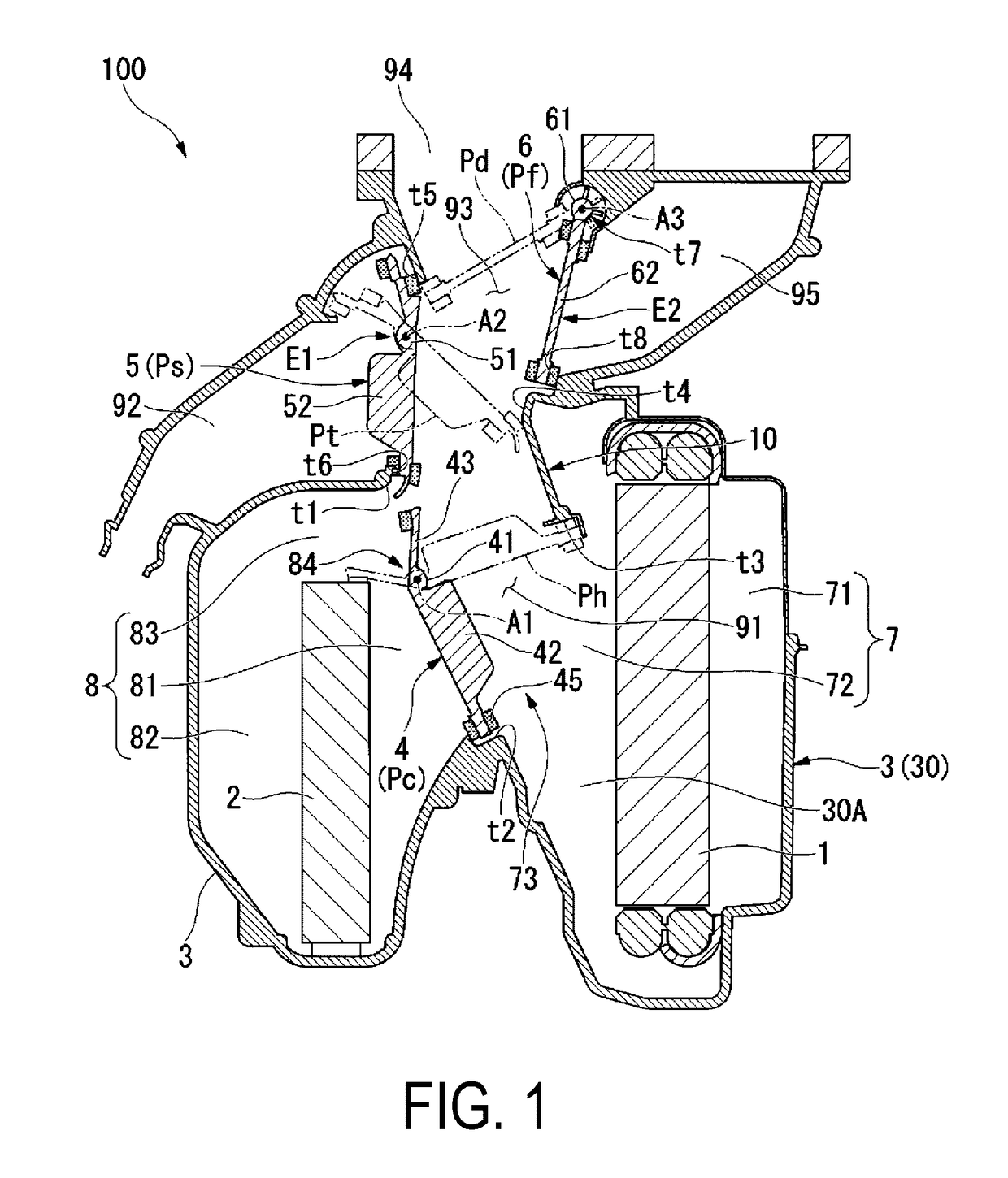
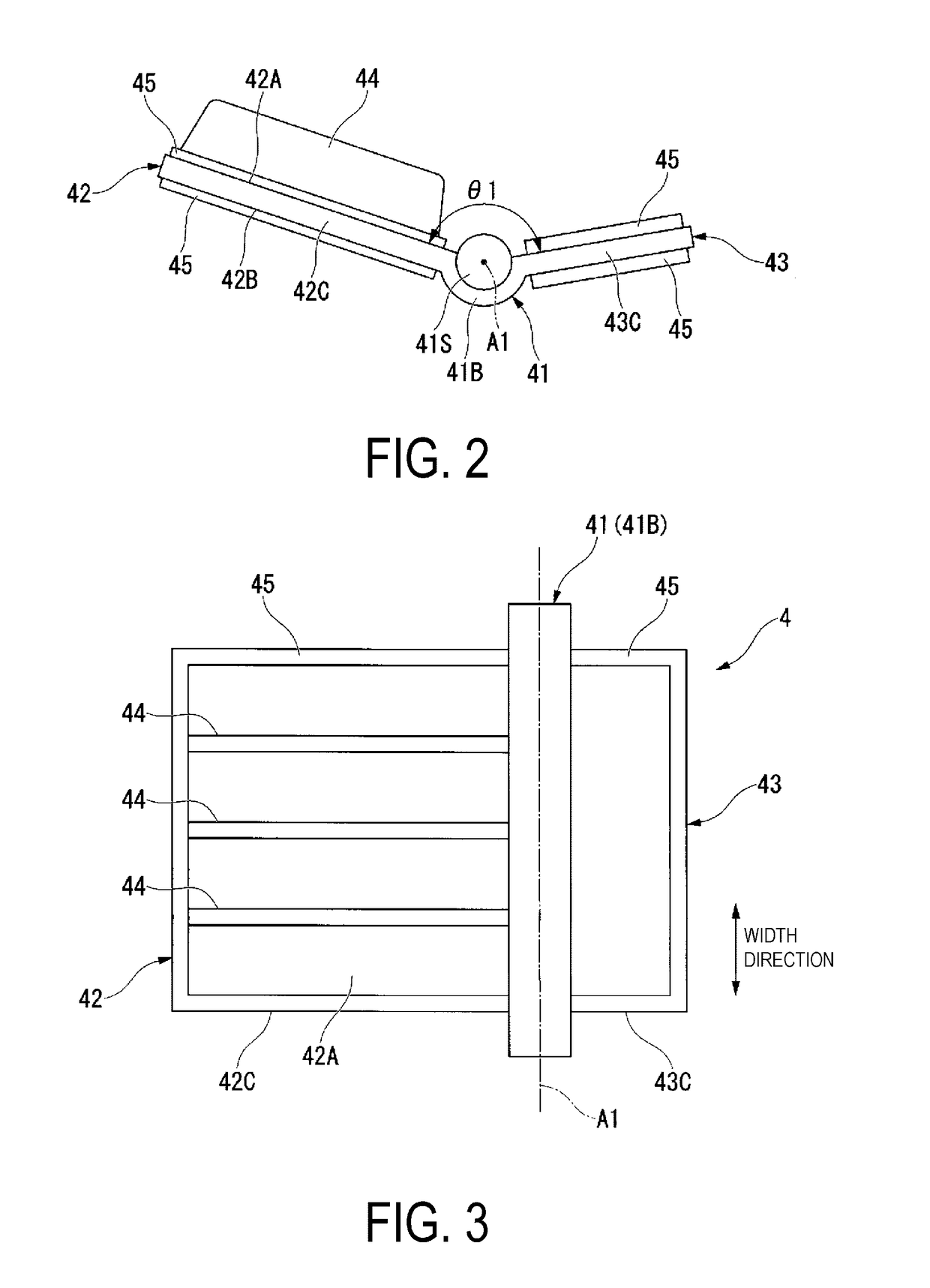
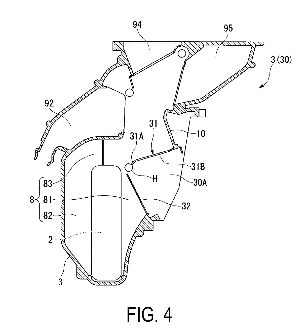
[0025]Embodiments of the present invention will be described below with reference to the drawings. As illustrated in FIG. 1, a vehicular air conditioning device 100 according to the present embodiment includes an evaporator 1, a heater core 2, a unit case 3 in which the evaporator 1 and the heater core 2 are accommodated, and an air mixing damper 4, a foot switching damper 5, and a face / defroster switching damper 6. The dampers 4, 5, and 6 adjust air flow inside the unit case 3.

[0026]FIG. 1 is a cross-sectional view of the vehicular air conditioning device 100 as viewed from the width direction transverse to the traveling direction of a vehicle on which the vehicular air conditioning device 100 is mounted. In the following description, the “as viewed in section” refers to a cross section as viewed in the width direction.

[0027]As the evaporator 1, a heat exchanger for cooling is used which employs a vapor compression refrigerating cycle, by way of example. A low-pressure refrigerant ...


PUM


Abstract

A vehicular air conditioning device includes a damper and a unit case in which a shaft receiving hole is formed for supporting the damper. The damper includes a rotating shaft portion extending in an axial direction, and a plate-like first damper body extending from the rotating shaft portion. The rotating shaft portion includes a flange portion provided at only a partial region in the circumferential direction of the axis. The inner wall surface of the unit case includes an elongated protrusion, with which a first damper plate surface of the first damper body is contactable from another side in the circumferential direction, and a contact portion with which a second damper plate surface of the first damper body is contactable from one side in the circumferential direction. A radial space between a radially inward end part of the elongated protrusion and a shaft receiving hole is less than a radial size of the flange portion.

Description

TECHNICAL FIELD[0001]The present invention relates to a vehicular air conditioning device.[0002]This application claims priority based on JP 2015-222024 filed in Japan on Nov. 12, 2015, of which the contents are incorporated herein by reference.BACKGROUND ART[0003]A vehicular air conditioning device used in an automobile and the like includes a heater core which is a heat exchanger for heating, an evaporator which is a heat exchanger for cooling, an air mixing space for mixing warm air that has passed through the heater core and cool air that has passed through the evaporator, and an air mixing damper for changing a mixing ratio between the warm air and cool air in the air mixing space. In such a device, a mixing ratio between the cool air and the warm air is changed by adjusting a pivot amount of the air mixing damper, and thus air with a desired temperature is obtainable.[0004]For the aforementioned device, from a view point of supplying air with uniform temperature distribution t...

Claims


Application Information

Patent Timeline
IPC IPC(8): B60H1/00B60H1/12B60H1/32
CPCB60H1/00678B60H1/00064B60H1/12B60H1/3227B60H2001/00714B60H2001/00707B60H1/00
Inventor KOMINAMI, SATOSHI
Owner MITSUBISHI HEAVY IND THERMAL SYST
Why Eureka
Try Eureka