Vehicle air-conditioner control system

a control system and air conditioner technology, applied in the direction of process control, lighting and heating apparatus, instruments, etc., can solve the problems of insufficient air conditioning, many air in the air-conditioned compartment may disadvantageously flow to the outside of the compartment, and none of the conventional air-conditioners described above have given due consideration to air-conditioning comfort, etc., to achieve sufficient air-conditioning and reduce the disagreeableness of air-conditioning wind and compressor nois

Inactive Publication Date: 2010-08-17
CALSONIC KANSEI CORP
View PDF18 Cites 45 Cited by
  • Summary
  • Abstract
  • Description
  • Claims
  • Application Information

AI Technical Summary

Benefits of technology

[0008]The present invention has been achieved in view of the above problems. According to the present invention, it is possible to provide a vehicle air-conditioner control system that can reduce disagreeableness of air-conditioning wind and compressor noise to thereby enable a passenger to board a vehicle comfortably, and that can avoid stopping an air-conditioner before the air-conditioner is activated again to be capable of sufficient air conditioning even in a strict environment by detecting that the passenger is proximate to the vehicle before the passenger is onboard and controlling the air-conditioner in a silent mode.

Problems solved by technology

However, none of the conventional air-conditioners described above have given due consideration to air-conditioning comfort when a passenger boards the vehicle.
The air-conditioning wind may strike against regions of the passenger's body other than those to which the air-conditioning wind is to be directed, making the passenger disadvantageously feel uncomfortable.
Furthermore, much air in the air-conditioned compartment may disadvantageously flow to the outside of the compartment.
Moreover, if the air conditioner operates in a case where a capacity of a compressor is relatively large, noise of the compressor may reach to the compartment, making the passenger disadvantageously feel uncomfortable.
Since the air conditioning finishes operating after the passenger boards the vehicle until the air-conditioner operates again, the vehicle may be insufficiently air-conditioned in an environment in which heat load is strict, making the passenger disadvantageously feel uncomfortable.

Method used


Image

  • Vehicle air-conditioner control system
  • Vehicle air-conditioner control system
  • Vehicle air-conditioner control system

Examples


first embodiment

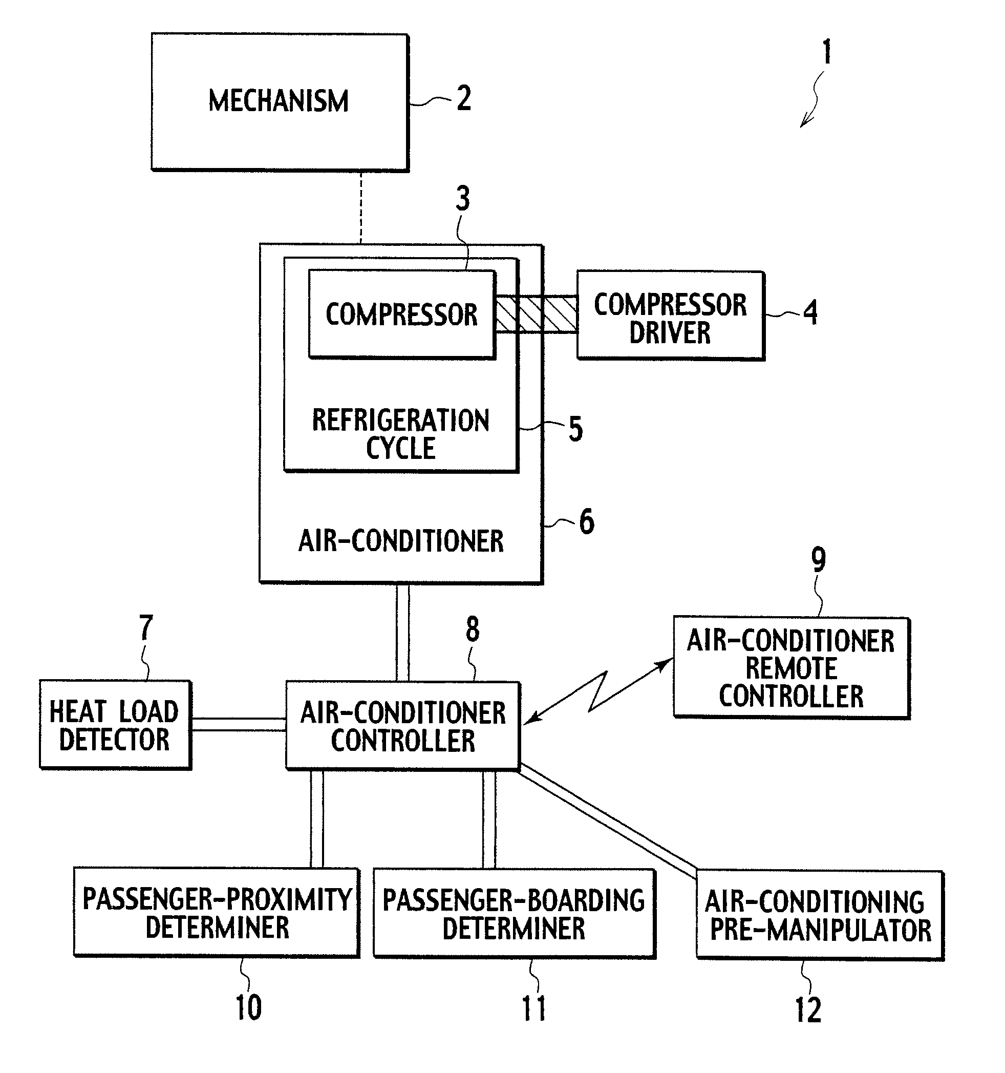
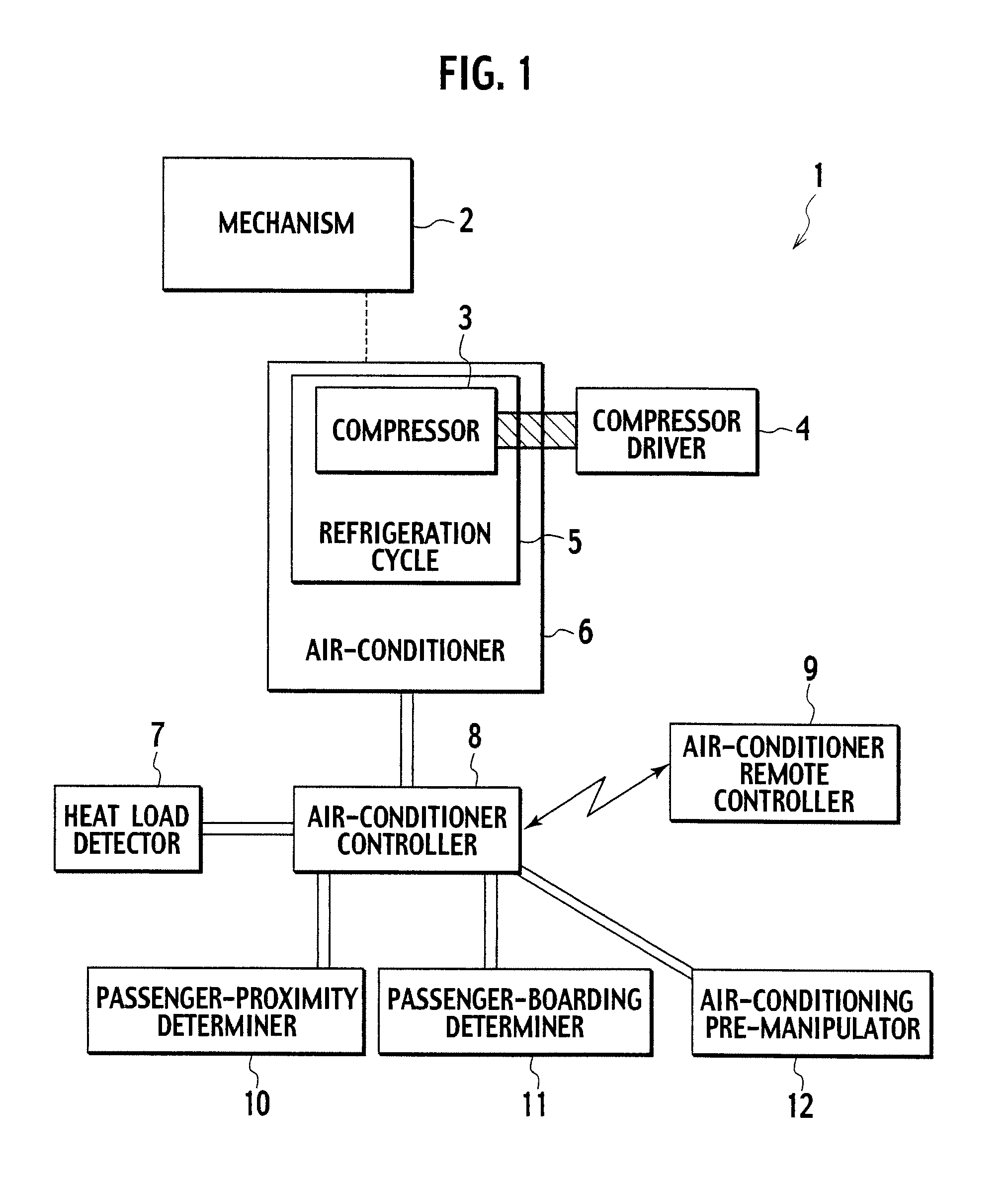
[0031]FIG. 1 is a block diagram showing a configuration of a vehicle air-conditioner control system according to a first embodiment.

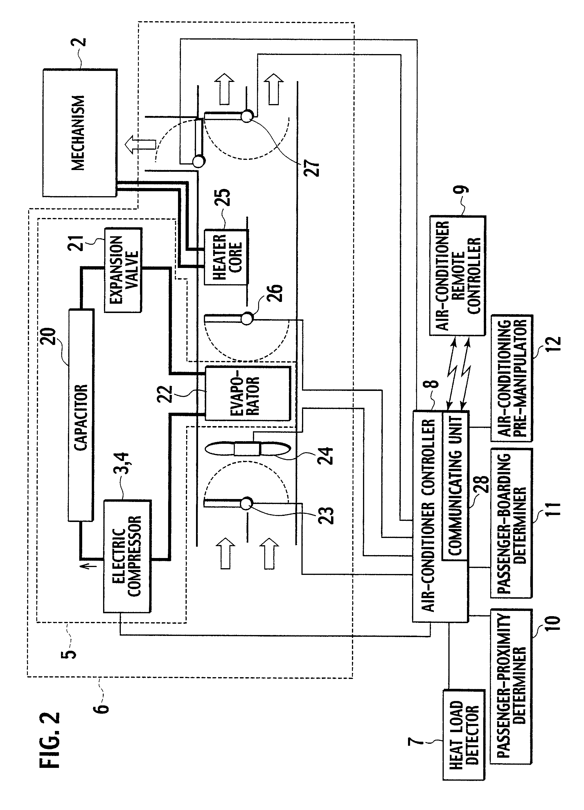
[0032]As shown in FIG. 1, a vehicle air-conditioner control system 1 according to the present embodiment includes a mechanism 2 (hereinafter, “engine 2” where appropriate) such as a motor or an engine that generates a driving force of a vehicle 40, a compressor 3 that pressurizes and compresses a refrigerant of a refrigeration cycle, a compressor driver 4 driving the compressor 3, a refrigeration cycle 5 including the compressor 3, a refrigeration cycle unit, a heat exchanger, a piping and the like, an air conditioner (air-conditioning unit) 6 that includes the refrigeration cycle 5 and that supplies an air-conditioning wind into a vehicle compartment, a heat load detector (heat load detecting unit) 7 configured to detect heat load imposed on the compartment (e.g., solar radiation, outdoor air temperature, and compartment temperature), an air-conditione...

second embodiment

[0076]A second embodiment of the present invention will be explained with reference to the drawings. FIG. 11 is a block diagram showing a configuration of a vehicle in which a vehicle air-conditioner control system according to the present embodiment is mounted.

[0077]As shown in FIG. 11, the vehicle in which the vehicle air-conditioner control system according to the present embodiment is mounted uses a battery 90 as a power supply, and a battery storage-capacity monitor 91 monitors a storage capacity of the battery. A current from the battery 90 is supplied, via a power-supply switch (power-supply switching unit) 99, to a driving inverter 92 and a compressor inverter 93. The driving inverter 92 communicates with the battery storage-capacity monitor 91, controls current consumption according to the storage capacity of the battery 90 to regenerate vehicle driving energy, and adjusts the storage capacity of the battery 90.

[0078]The current supplied to the driving inverter 92 is suppli...

third embodiment

[0090]A third embodiment of the present invention will be explained with reference to the drawings. FIG. 13 is a block diagram showing a configuration of a vehicle in which a vehicle air-conditioner control system according to the present embodiment is mounted. As shown in FIG. 13, differently from the second embodiment, the vehicle mounting the vehicle air-conditioner control system according to the present embodiment includes a driving power-supply switch (driving power-supply switching unit) 103 that is provided between a battery 90 and a driving inverter 92, and a compressor power-supply switch (air-conditioner power-supply switching unit) 104 that is provided between the battery 90 and a compressor inverter 93. Since the other constituent elements of the vehicle in which the vehicle air-conditioner control system according to the present embodiment are identical with those according to the second embodiment, detailed explanations thereof will be omitted.

[0091]In the vehicle air...


PUM


Abstract

A vehicle air-conditioner control system according to the present invention activates an air conditioner in response to a command from an air-conditioner remote controller before a passenger is onboard, controls the air conditioner based on a heat load detected by a heat load detector, controls the air conditioner to be set in a silent mode so as not to make the passenger feel uncomfortable due to an air-conditioning wind when a passenger-proximity determiner determines that the passenger is proximate to the vehicle.

Description

TECHNICAL FIELD[0001]The present invention relates to a vehicle air-conditioner control system that air-conditions a vehicle by remote control before a passenger boards the vehicle, and more particularly relates to a vehicle air-conditioner control system that executes control of air-conditioning so as not to make a passenger feel uncomfortable with air-conditioning wind by changing over an air-conditioning mode to a silent mode particularly when the passenger is proximate to the vehicle.BACKGROUND ART[0002]There is conventionally known a technique for performing air conditioning of a vehicle by remote control. It is disclosed, for example, in Japanese Utility Model Application Laid-Open No. 61-174250 to activate an air-conditioning unit or the like before arrival of a passenger at a vehicle by remote-controlling vehicle equipment over a telephone outside the vehicle.[0003]Furthermore, it is disclosed in Japanese Patent Application Laid-Open No. 5-147420 to calculate a passenger boa...

Claims


Application Information

Patent Timeline
Patent Type & Authority Patents(United States)
IPC IPC(8): G05D23/00B60H1/32B61D27/00
CPCB60H1/00642B60H1/00657B60H1/00742B60H1/00771B60H1/00828B60H2001/006
Inventor HARA, JUNICHIRO
Owner CALSONIC KANSEI CORP
Why Eureka
Try Eureka