Multi-source stimulation

Inactive Publication Date: 2018-12-20
NEWSOUTH INNOVATIONS PTY LTD
View PDF1 Cites 0 Cited by
  • Summary
  • Abstract
  • Description
  • Claims
  • Application Information

AI Technical Summary

Problems solved by technology

One problem with implementing these electrode arrays is the trade-off between high density of electrodes providing better visual acuity in the implant recipient and the interference between adjacent stimulating electrodes.
The amount of electric charge that is required from a given stimulation strategy in order to elicit a response from the neurons increases with distance and may eventually require more electric charge than may be safely, effectively or otherwise practically be delivered.

Method used


Image

  • Multi-source stimulation
  • Multi-source stimulation
  • Multi-source stimulation

Examples


Embodiment Construction

[0040]In one application the present invention is applied to a retinal neuroprosthesis. In other applications described below the invention is applied in deep brain stimulation of the sub-thalamic nucleus or stimulation of the auditory system via the cochlea.

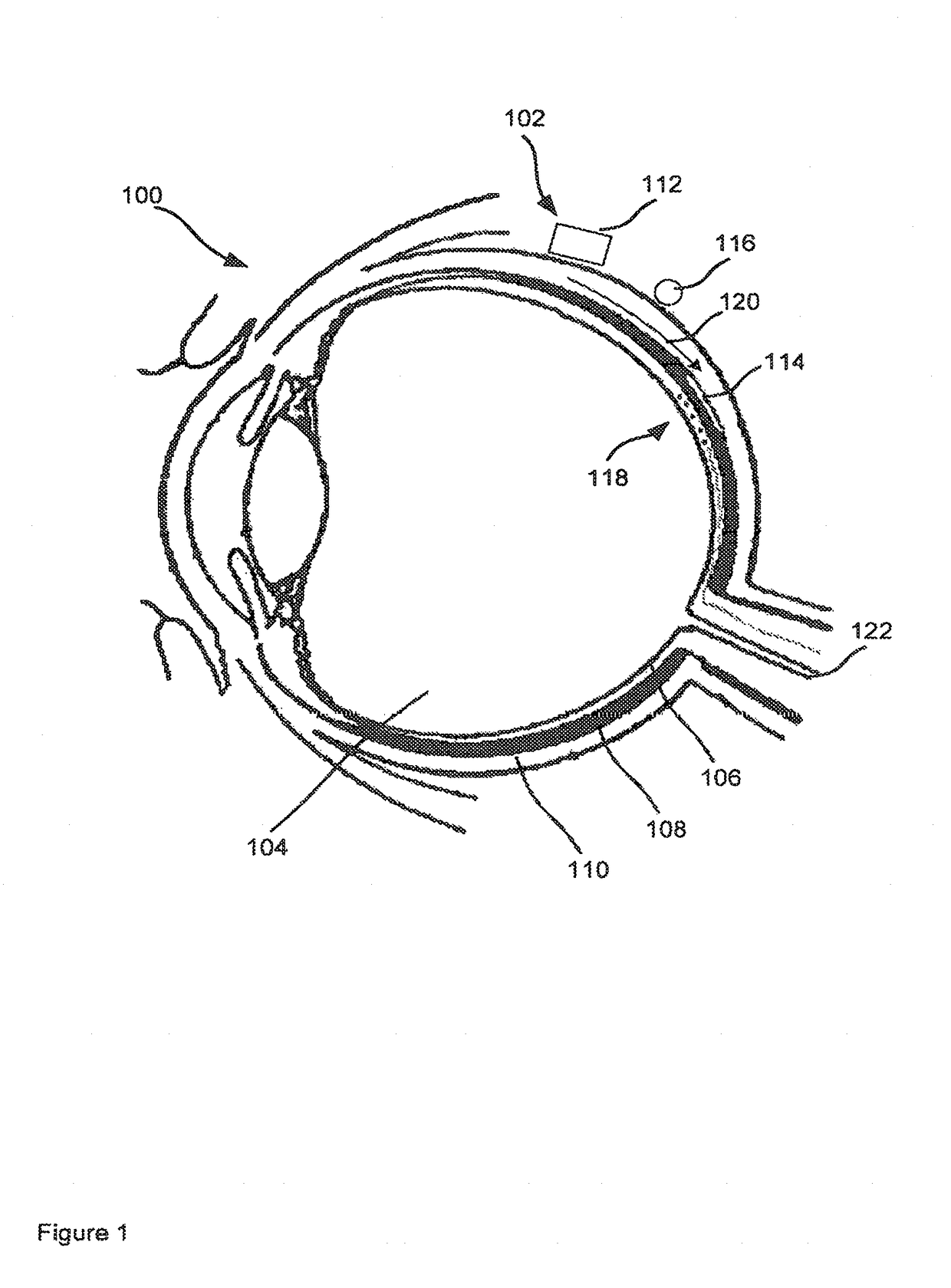
[0041]FIG. 1 shows a cross section of an eye 100 with the implanted portion of a retinal prosthesis 102. The eye 100 includes three layers bounding the vitreous humour 104: the neural retina 106, choroid 108 and sclera 110.

[0042]The prosthesis 102 includes at least one electronics capsule 112, an electrode array 114 and at least one monopolar return electrode 116. When implanting these components of the prosthesis the electrode array 114 is inserted into the eye to be near to the neurons 118 that lie in the neural retina 106 and that need to be stimulated. However, the choroid 108 is the vascular layer of the eye so that incisions may result in unwanted bleeding. Therefore, one method of inserting the electrode array 114 without...


PUM


Abstract

A system and method are described for stimulating excitable tissue. The system includes a monopolar stimulation source that generates a sub-threshold field in the vicinity of the excitable tissue, the sub-threshold field being below a threshold at which activation of the excitable tissue occurs. One or more local stimulation sources generate a local field, which in combination with the sub-threshold field exceeds the threshold of the excitable tissue.

Description

FIELD OF THE INVENTION[0001]The present invention relates to systems and methods for electronic stimulation of tissue. In one form the invention relates to neural stimulation electrodes for retinal prostheses.BACKGROUND OF THE INVENTION[0002]Retinal prosthetic devices may use electrode arrays to deliver electrical pulses to the retina in order to evoke patterned light perception. The electrodes evoke perception of phosphenes via remaining intact retinal neurons of vision-impaired users. One problem with implementing these electrode arrays is the trade-off between high density of electrodes providing better visual acuity in the implant recipient and the interference between adjacent stimulating electrodes. Consequently improved methods of implementing electrode arrays are desirable in order to effect neural stimulation through the elicitation of substantially discrete phosphenes.[0003]Another trade-off involves the distance between the stimulating electrodes and the neurons targeted ...

Claims


Application Information

Patent Timeline
Patent Type & Authority Applications(United States)
IPC IPC(8): A61N1/36A61N1/05
CPCA61N1/36164A61N1/36046A61N1/0543
Inventor MATTEUCCI, PAUL BRENDONSUANING, GREGG JORGEN
Owner NEWSOUTH INNOVATIONS PTY LTD
Why Eureka
Try Eureka