Autostable bicanalicular probe

a bicanalicular and probe technology, applied in the field of bicanalicular probes, can solve problems such as difficulty for surgeons to manipulate, and achieve the effects of less traction, less traction, and avoiding the phenomenon of “cheese wiring”

Active Publication Date: 2019-01-31
FRANCE CHIRURGIE INSTR F C I
View PDF3 Cites 0 Cited by
  • Summary
  • Abstract
  • Description
  • Claims
  • Application Information

AI Technical Summary

Benefits of technology

[0012]According to an improvement, a mark is provided half way between the two tubes to assist in positioning by the surgeon.
[0013]Providing such a bicanalicular probe according to the invention, the surgeon can ensure that when fitting the probe, the two tubes are placed in the lacrimal sac and not in the horizontal part of the canalicules or in the nasolacrimal duct. The probe is therefore more mobile and free in position in the duct creating less traction on the meati and avoiding “Cheese wiring” phenomena. Furthermore, it is no longer necessary to tie the silicone strands after fitting, withdrawal being effected by pulling on the central segment, and it is no longer necessary to cut the knot in the nose.
[0014]The stability of the probe is particularly good, due to the presence of two tubes in the sac. Finally, the central mark assists in positioning the probe when fitting by pulling on the strands of the terminations in such a way that the tubes are precisely located in the sac.

Problems solved by technology

These early devices, although constituting a particularly appropriate solution for insertion into the nasolacrimal duct, are difficult for the surgeon to manipulate to obtain the correct position in the nasolacrimal duct and require the strands of the central tube to be tied after fitting.

Method used


Image

  • Autostable bicanalicular probe

Examples


Embodiment Construction

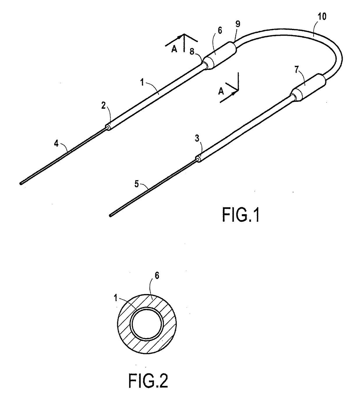
[0018]FIG. 1 shows a bicanalicular probe intended to be inserted into the nasolacrimal duct of a patient. This probe consists of a silicone tube 1 that extends between two end points 2 and 3. Two termination parts 4 and 5 protrude from the end points 2 and 3 and enable the probe to be inserted. The parts 4 and 5 are thinner than the tube 1.

[0019]These termination parts can be guide wires, preferably in PEEK, as described in patent FR-A-2992851 and in which the tube / guide wire joint is chamfered to prevent any roughness from rubbing against the nasal wall during insertion.

[0020]The parts 4 and 5 may also be mandrels as shown in the document U.S. Pat. No. 4,380,239 in which the tube / mandrel joint is also chamfered. They may also be mandrels, preferably of external diameter 0.80 mm and length 80 mm, assembled with the silicone tube 1 as described in patent FR-A-2700722. They may also be metal mandrels of external diameter 0.4 mm and length 60 mm bonded to the inside of the silicone tub...


PUM


Abstract

A bicanalicular probe intended to be inserted into the nasolacrimal duct of a patient including a central tubular part 1 made from a material compatible with insertion into the human body, preferably silicone, and two termination parts 4, 5 each fixed to one end of the central tubular part 1, characterized in that the two thickened parts 6, 7 project from the central tubular part, the two thickened parts being firstly at a distance from each other and secondly each at a distance from the ends 2, 3 where the termination parts are attached.

Description

TECHNICAL FIELD[0001]The present invention relates to a bicanalicular probe intended to be inserted into the nasolacrimal duct of a patient.BACKGROUND ART[0002]Classically, a bicanalicular probe intended to be inserted into the nasolacrimal duct of a patient comprises a central tube forming a probe made from a material compatible with insertion into the human body, notably silicone, that is connected at its opposite ends to termination parts, for example guide wires, mandrels or the like, that permit the introduction of the central silicone tube into the nasolacrimal duct.[0003]These early devices, although constituting a particularly appropriate solution for insertion into the nasolacrimal duct, are difficult for the surgeon to manipulate to obtain the correct position in the nasolacrimal duct and require the strands of the central tube to be tied after fitting. U.S. Pat. No. 6,117,116, describes a probe according to the preamble of claim 1. A tube is formed at the interface betwee...

Claims


Application Information

Patent Timeline
Patent Type & Authority Applications(United States)
IPC IPC(8): A61F9/007
CPCA61F9/00772A61B17/12022
Inventor JONCKHEERE, PAULFERRON, ABRAHAM
Owner FRANCE CHIRURGIE INSTR F C I
Why Eureka
Try Eureka