
Padded Hand Restraint

a hand restraint and padded technology, applied in the field of hand restraint devices, can solve the problems of not having padding on the mittens applied, requiring a greater amount of attention, and not being able to use the iv in the hand, etc., to achieve the effect of convenient use, convenient and quick access, and safe operation

Inactive Publication Date: 2019-04-11
NATOLE RENEE
View PDF0 Cites 3 Cited by
  • Summary
  • Abstract
  • Description
  • Claims
  • Application Information

AI Technical Summary

Benefits of technology

The present invention provides a new and improved hand restraint device that is convenient, safe, and comfortable for users. It consists of a padded base that can be attached to a stationary object, a wrist strap, and a mesh netting for additional security. This device allows for easy and efficient restraint of patients, providing a significant improvement over existing hand restraints.

Problems solved by technology

Many patients who are confused or are suffering from severe injuries require special care, and often require restraints while in a hospital bed.
These patients require a greater than usual amount of attention from the nursing staff, as they are prone to attempting to remove their IVs or other equipment, thereby further injuring themselves.
However, the mittens applied do not have padding and are uncomfortable for most patients.
Unfortunately, when the patient's hand is covered by a typical mitten, an IV is either no longer usable in that hand or it is difficult to see how successfully the IV is inserted into the hand.
Additionally, the mitten and wrist restraint are typically separate devices that are not kept together, requiring the nurse to find multiple pieces of equipment to restrain the patient.
Further, it is difficult to apply these devices, and additionally difficult to find an appropriate size for the patient.

Method used


Image

  • Padded Hand Restraint
  • Padded Hand Restraint
  • Padded Hand Restraint

Examples


Embodiment Construction

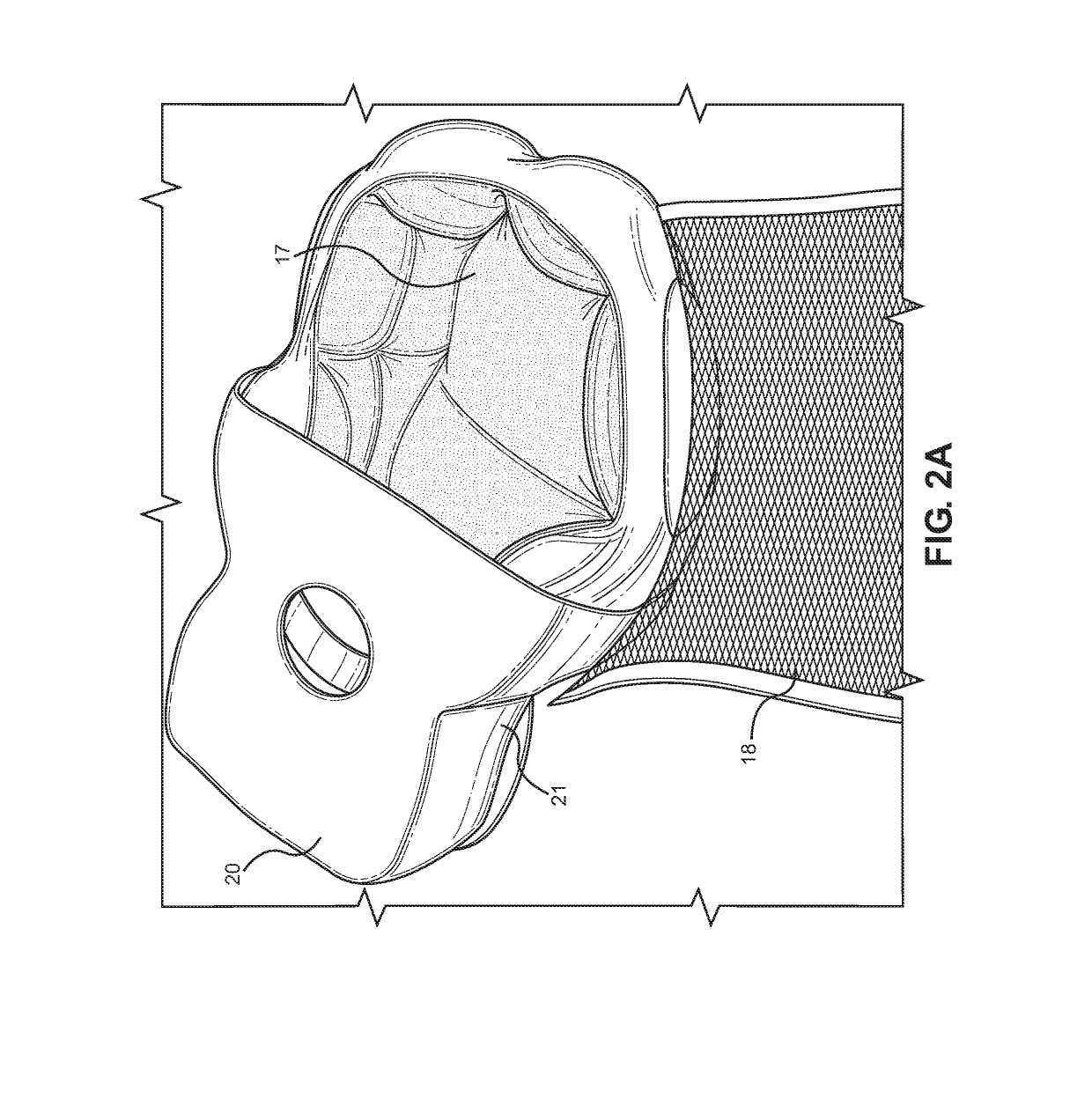
[0015]Reference is made herein to the attached drawings. Like reference numerals are used throughout the drawings to depict like or similar elements of the padded hand restraint. The figures are intended for representative purposes only and should not be considered to be limiting in any respect.

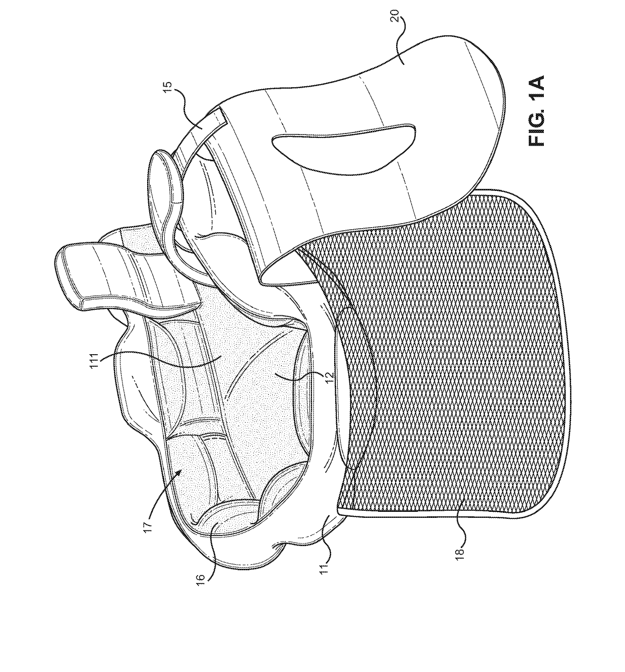
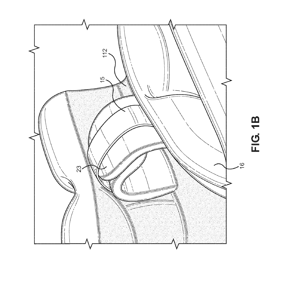
[0016]Referring now to FIG. 1A and FIG. 1B, there is shown a perspective view of an embodiment of the padded hand restraint with the netting and secondary wrist strap unfastened, and a close-up perspective view of an embodiment of the padded hand restraint with the wrist strap fastened, respectively. A padded hand restraint comprises a padded base 11 having an upper surface 12 and a lower surface 13 (as seen in FIG. 4). The padded base 11 comprises an annularly shaped portion 111 with a generally straight protrusion 112 along a rear portion of the perimeter, such that a mitten shape is formed. The padded base 11 is configured to receive a wrist along the protrusion 112 and a hand in an open p...


PUM


Abstract

A padded hand restraint for securing a hand and wrist to a bed frame. The padded hand restraint includes an annularly shaped padded base with an elongated portion designed to receive a hand and a wrist. A lower strap designed to secure the padded base to an object is attached to a lower surface of the padded base. A wrist strap designed to secure a wrist is disposed on an upper surface. A peripheral padding extends outwardly along a perimeter of the padded base, forming an open section. A secondary strap designed to further secure the wrist is disposed on the elongated portion of the peripheral padding. A mesh netting is additionally located along the annular portion of the padded base, the netting designed to secure over the open section such that the hand is visible while restrained. In this way, a patient can be removably restrained in an efficient manner.

Description

CROSS REFERENCE TO RELATED APPLICATIONS[0001]This application claims the benefit of U.S. Provisional Application No. 62 / 570,836 filed on Oct. 11, 2017. The above identified patent application is herein incorporated by reference in its entirety to provide continuity of disclosure.BACKGROUND OF THE INVENTION[0002]The present invention relates to hand restraint devices. More specifically, the present invention provides a padded base having an upper surface and a lower surface, wherein the lower surface has a lower strap disposed thereon and the upper surface is configured to receive a hand. A wrist strap is disposed on the upper surface and configured to secure a wrist to the padded base. A peripheral padding extends outward from the upper surface, thereby forming an open portion, wherein a mesh netting and secondary wrist strap disposed along an outer surface of the peripheral padding are configured to removably secure overtop the upper portion, thereby enclosing the hand and wrist.[0...

Claims


Application Information

Patent Timeline
Patent Type & Authority Applications(United States)
IPC IPC(8): A41D19/015A41D19/01A61F5/37
CPCA41D19/01582A41D19/01A61F5/3761A61F5/3769A41D19/0048
Inventor NATOLE, RENEE
Owner NATOLE RENEE
Learn More