
Multiplexer, radio-frequency front-end circuit, and communication device

a radio frequency front-end circuit and multi-channel technology, applied in the direction of impedence networks, electrical equipment, transmission, etc., can solve the problem of degrading the characteristics of another filter, and achieve the effect of reducing or preventing a ripple in a pass band

Active Publication Date: 2019-04-25
MURATA MFG CO LTD
View PDF0 Cites 43 Cited by
  • Summary
  • Abstract
  • Description
  • Claims
  • Application Information

AI Technical Summary

Benefits of technology

The patent is about creating devices that can prevent or reduce a ripple in the pass band. This means that they can improve the quality of the signal by minimizing the distortion. This technology is useful for multiplexers, RF front-end circuits, and communication devices.

Problems solved by technology

Thus, the characteristics of one filter that do not affect the one filter may become a factor that degrades the characteristics of another filter.
However, if the frequency at which the stop-band ripple is generated is within the pass band of another filter, this may become a factor that increases a ripple in the pass band (a pass-band ripple) of the other filter.

Method used


Image

  • Multiplexer, radio-frequency front-end circuit, and communication device
  • Multiplexer, radio-frequency front-end circuit, and communication device
  • Multiplexer, radio-frequency front-end circuit, and communication device

Examples


first preferred embodiment

[0043]In a first preferred embodiment of the present invention, a quadplexer will be described as an example of a preferred multiplexer.

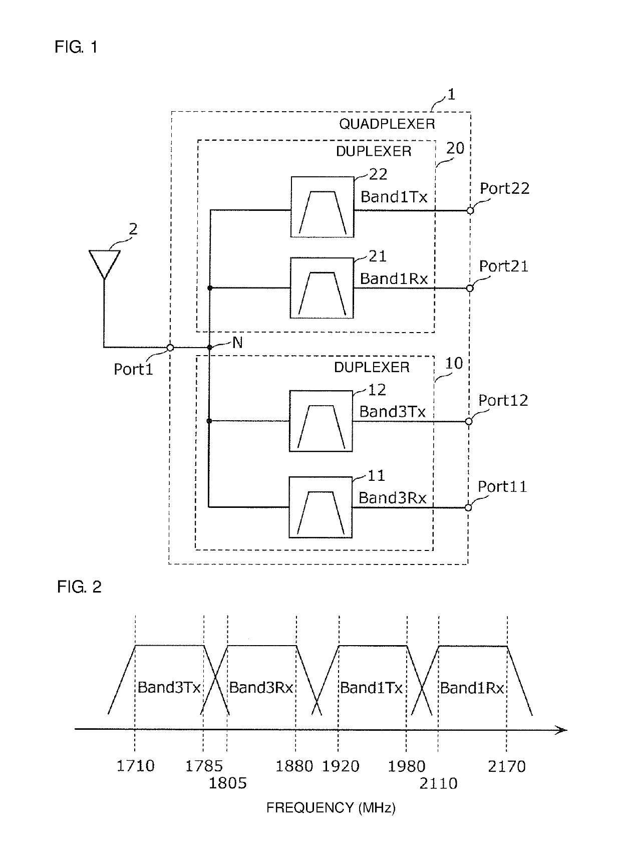
[0044]FIG. 1 is a configuration diagram of a quadplexer 1 according to the present preferred embodiment. FIG. 1 also illustrates an antenna element 2 that is connected to a common terminal Port1 of the quadplexer 1.

[0045]The quadplexer 1 is a multiplexer (band separator) that includes a plurality of filters (here, four filters 11, 12, 21, and 22) having different pass bands and that includes a common terminal Port1 defining and functioning as antenna-side terminals of the plurality of filters.

[0046]Specifically, as illustrated in FIG. 1, the quadplexer 1 includes the common terminal Port1, four individual terminals Port11, Port12, Port21, and Port22, and the four filters 11, 12, 21, and 22.

[0047]The common terminal Port1 is commonly provided for the four filters 11, 12, 21, and 22 and is connected to these filters 11, 12, 21, and 22 in the inner sid...

second preferred embodiment

[0130]The quadplexers according to the first preferred embodiment and the Modified Example are applicable to an RF front-end circuit and also to a communication device including the RF front-end circuit. In the present preferred embodiment, a description will be provided of the RF front-end circuit and the communication device.

[0131]FIG. 10 is a configuration diagram of an RF front-end circuit 30 according to the second preferred embodiment. FIG. 10 also illustrates the individual elements connected to the RF front-end circuit 30 (the antenna element 2, an RF signal processing circuit (RFIC) 3, and a baseband signal processing circuit (BBIC) 4). The RF front-end circuit 30, the RF signal processing circuit 3, and the baseband signal processing circuit 4 define a communication device 40.

[0132]The RF front-end circuit 30 includes the quadplexer 1 according to the first preferred embodiment, a reception-side switch 13 and a transmission-side switch 23, a low-noise amplification circuit...


PUM


Abstract

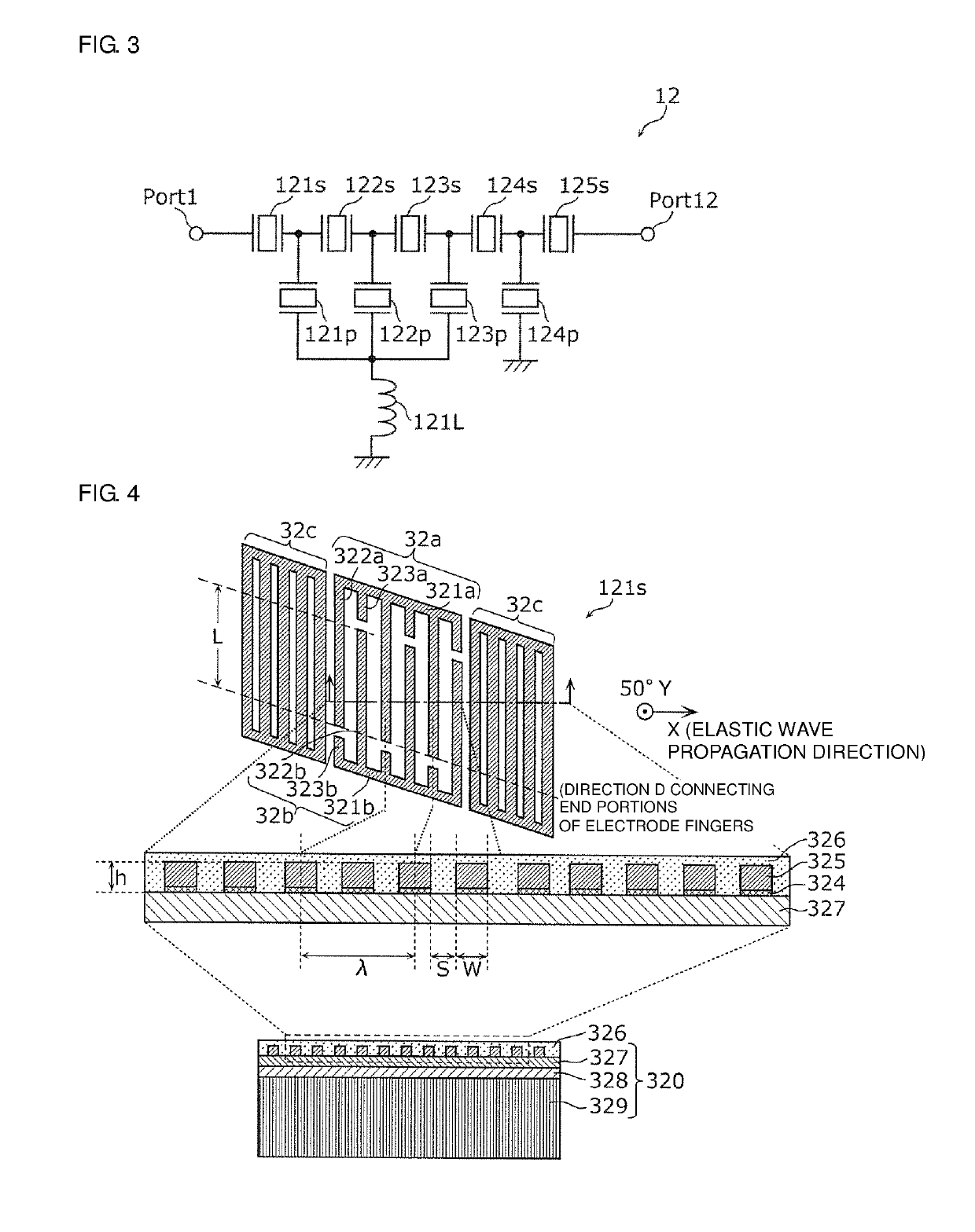
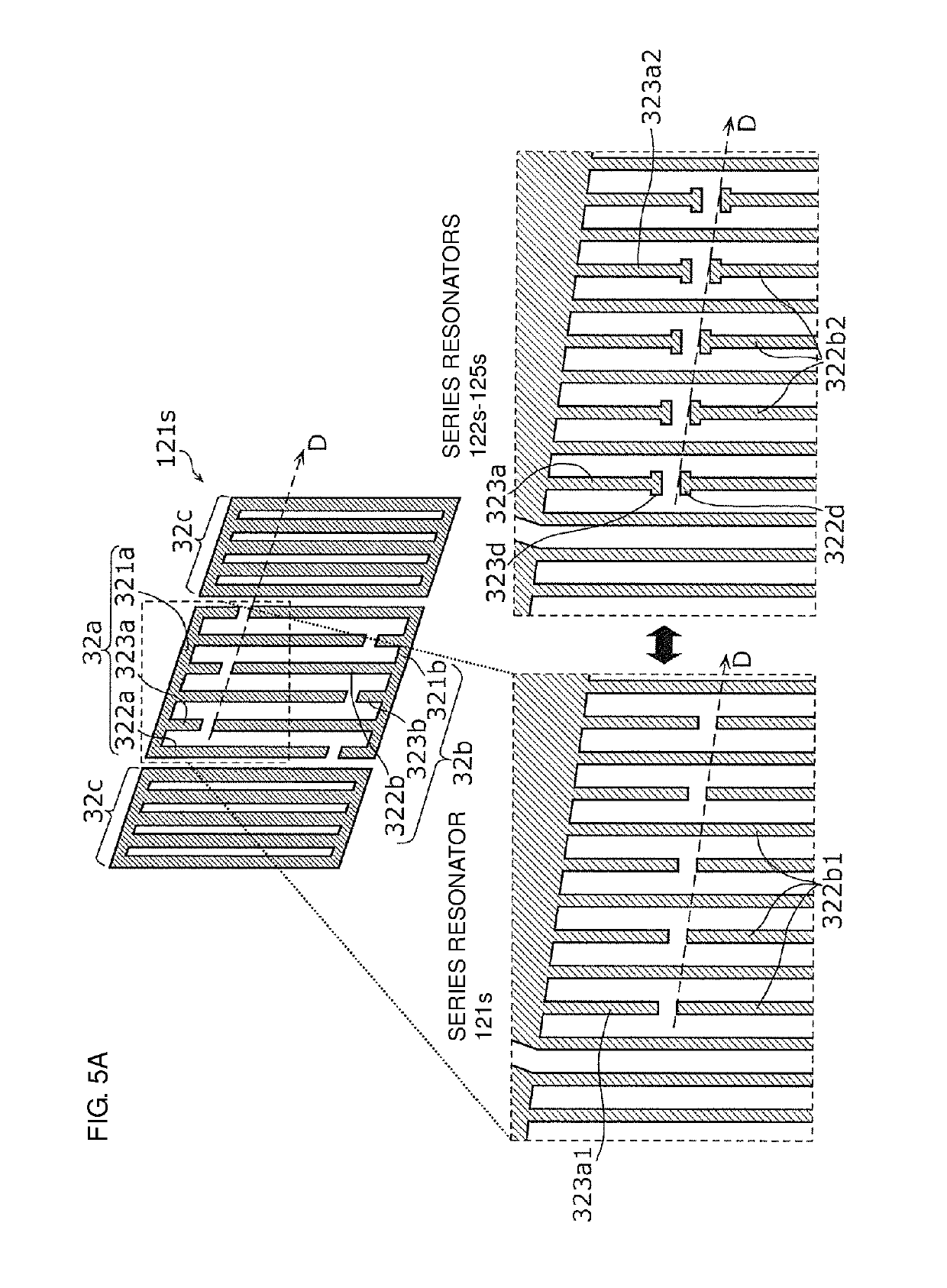
A quadplexer includes a first filter and a second filter having a pass band frequency that is higher than a pass band frequency of the first filter. The first filter includes series resonators disposed on a first path and parallel resonators disposed on a path that connects the first path and a ground to each other. A direction that connects ends of a plurality of electrode fingers defining each resonator crosses an elastic wave propagation direction at a predetermined angle. The series resonator nearest to a common terminal does not include first electrode fingers, and the other series resonators include the first electrode fingers.

Description

CROSS REFERENCE TO RELATED APPLICATIONS[0001]This application claims the benefit of priority to Japanese Patent Application No. 2016-128184 filed on Jun. 28, 2016 and is a Continuation Application of PCT Application No. PCT / JP2017 / 016746 filed on Apr. 27, 2017. The entire contents of each application are hereby incorporated herein by reference.BACKGROUND OF THE INVENTION1. Field of the Invention[0002]The present invention relates to a multiplexer, a radio-frequency (RF) front-end circuit, and a communication device.2. Description of the Related Art[0003]In recent years, band separators for splitting (separating) an RF signal into frequency bands have been widely used in communication devices, such as cellular phone terminals, so that a single terminal supports a plurality of frequency bands and a plurality of radio systems, that is, multiband and multimode operations. For such a band separator, there has been proposed a configuration in which two duplexers are combined into a quadpl...

Claims


Application Information

Patent Timeline
Patent Type & Authority Applications(United States)
IPC IPC(8): H03H9/64H03H9/145H03H9/02
CPCH03H9/6406H03H9/6496H03H9/14502H03H9/02992H03H9/14541H03H9/145H03H9/64H03H9/72H03H9/725H03H9/6483H04B1/0057H03H9/14544
Inventor TAKAMINE, YUICHI
Owner MURATA MFG CO LTD
Learn More