Wireless scanner

Inactive Publication Date: 2019-05-02
ETHER CAPITAL CORP
View PDF0 Cites 0 Cited by
  • Summary
  • Abstract
  • Description
  • Claims
  • Application Information

AI Technical Summary

Benefits of technology

The present invention relates to a scanner system for calibrating and correcting measurements made using a very near-field scanner of an antenna-under-test (AUT) or device-under-test (DUT). The scanner uses a probe array consisting of a plurality of antenna probes and RF receivers to capture near-field data in proximity of the AUT or DUT. The scanner transforms the near field data into far-field data or represents currents on the DUT related to the measurements using a far field transformation method. The technical effects of the invention include improved accuracy and efficiency of measurements, reduced interference and noise, and simplified data processing.

Problems solved by technology

Near-field measurement systems are widely used for the characterization of large and / or low frequency antennas for which far-field or compact range measurement systems become too costly and in some cases impractical to use.

Method used


Image

  • Wireless scanner
  • Wireless scanner
  • Wireless scanner

Examples


Embodiment Construction

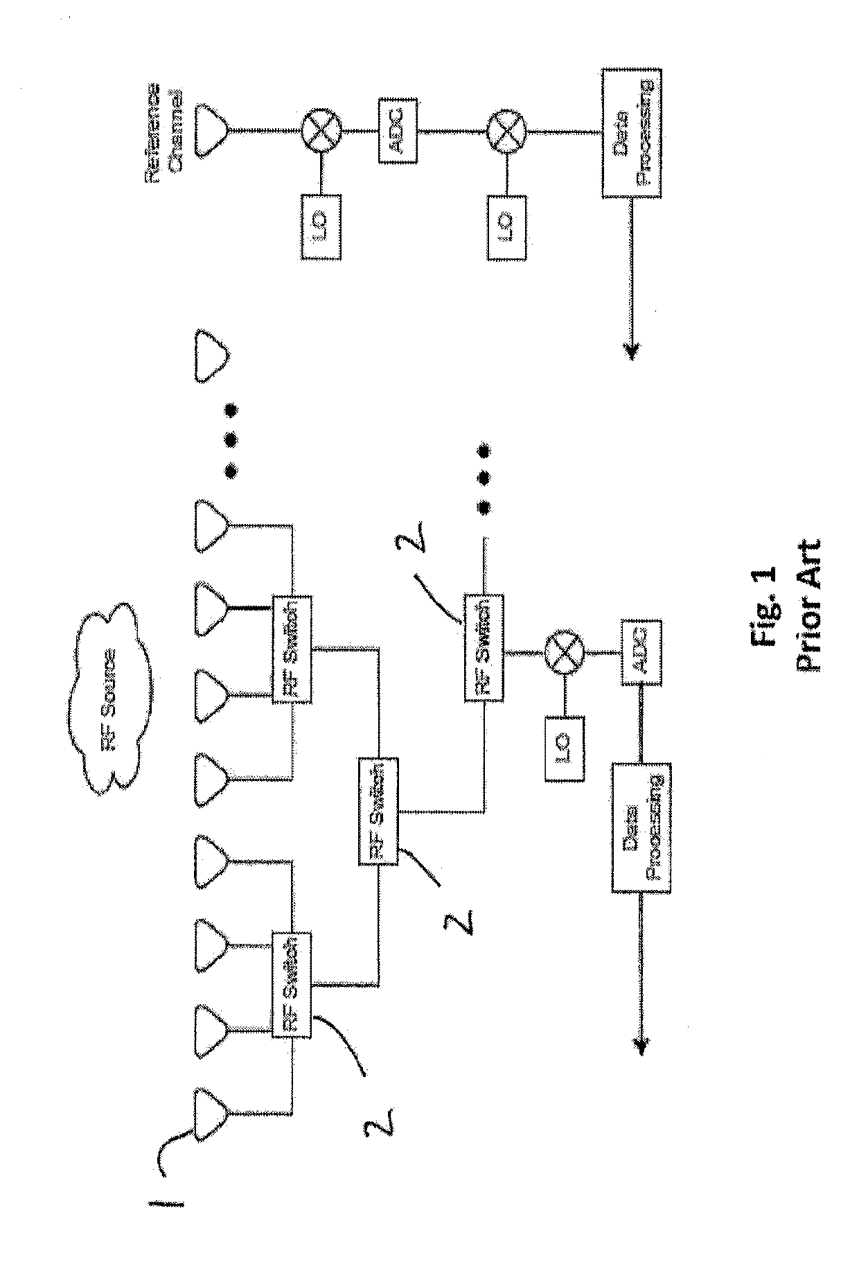
[0019]Conventional antenna measurement devices which use an array of integrated antenna probes that are electronically switched so that a large number of probes may be arrayed with a relatively fewer number of RF receivers. Exemplary devices include those described in U.S. Pat. No. 8,502,546, the entire contents of which are incorporated herein by reference, for all purposes, where permitted. As shown in prior art FIG. 1, the output from a specific probe (1) is selected by means of layered RF switches (2) which can select the output from any one of the probes. Multichannel near field measurement systems and near-field to far-field transformations are described in co-owned U.S. Pat. No. 8,502,546, the entire contents of which are incorporated herein by reference, where permitted.

[0020]The system shown in FIG. 1 sequentially selects each probe to go to a single RF receiver (downconverter and ADC) that will measure magnetic field amplitude and / or phase. The sequential selection is done...


PUM


Abstract

An RF scanning system and method includes a plurality of antenna probes and a plurality of RF receivers, wherein each probe is associated with a unique RF receiver, which outputs data to a digital signal processor.

Description

FIELD OF THE INVENTION[0001]The present invention relates to systems and methods of measurement for characterizing antenna performance.BACKGROUND[0002]Near-field measurement systems are widely used for the characterization of large and / or low frequency antennas for which far-field or compact range measurement systems become too costly and in some cases impractical to use. Near-field measurement systems are also used to investigate the near-field emissions from electrical devices to identify problems related to unintentional radiated emissions. In both applications, the compact size of these near-field measurement systems allows for integration of measurement probes in planar, circular, and other array configurations. If the measurements are done by an array of sensors, the mechanical movements of the probes, the antenna-under-test (AUT) or device-under-test (DUT) are reduced or eliminated, and hence the measurement time is reduced. In the case of planar near-field antenna measuremen...

Claims


Application Information

Patent Timeline
IPC IPC(8): G01R29/08
CPCG01R29/0871G01R29/10
Inventor PATTON, RUSKAAL-ROBAEE, SAMMERMONTAG, GIL
Owner ETHER CAPITAL CORP
Why Eureka
Try Eureka