System and method for cargo delivery

a cargo and system technology, applied in the field of air cargo, can solve the problems of increasing the difficulty of these operations, and none of the documents disclose a delivery system capable of receiving cargo

Active Publication Date: 2019-05-09
DRONE FUTURE BVBA
View PDF4 Cites 16 Cited by
  • Summary
  • Abstract
  • Description
  • Claims
  • Application Information

AI Technical Summary

Benefits of technology

[0014]d. transferring the cargo and / or passengers respectively to the cargo module from the receiving station or from the cargo module to the receiving station; and
[0016]A method according to an embodiment of the invention is particularly suitable for home delivery of packages, especially in heavily populated areas. The packages may vary and can range from medicines, food, electronics, newspaper or other written media, etc. . . . .

Problems solved by technology

. . ), which greatly increases the difficulty of these operations.
Furthermore, none of the documents discloses a delivery system that is capable of receiving cargo from different types of drones, either having detachable cargo modules, or where the cargo module is inseparable from the aerial vehicle.

Method used


Image

  • System and method for cargo delivery
  • System and method for cargo delivery
  • System and method for cargo delivery

Examples


example 1

hicle, Preferably UAV, is Conveyed Between Docking Station and Receiving Station

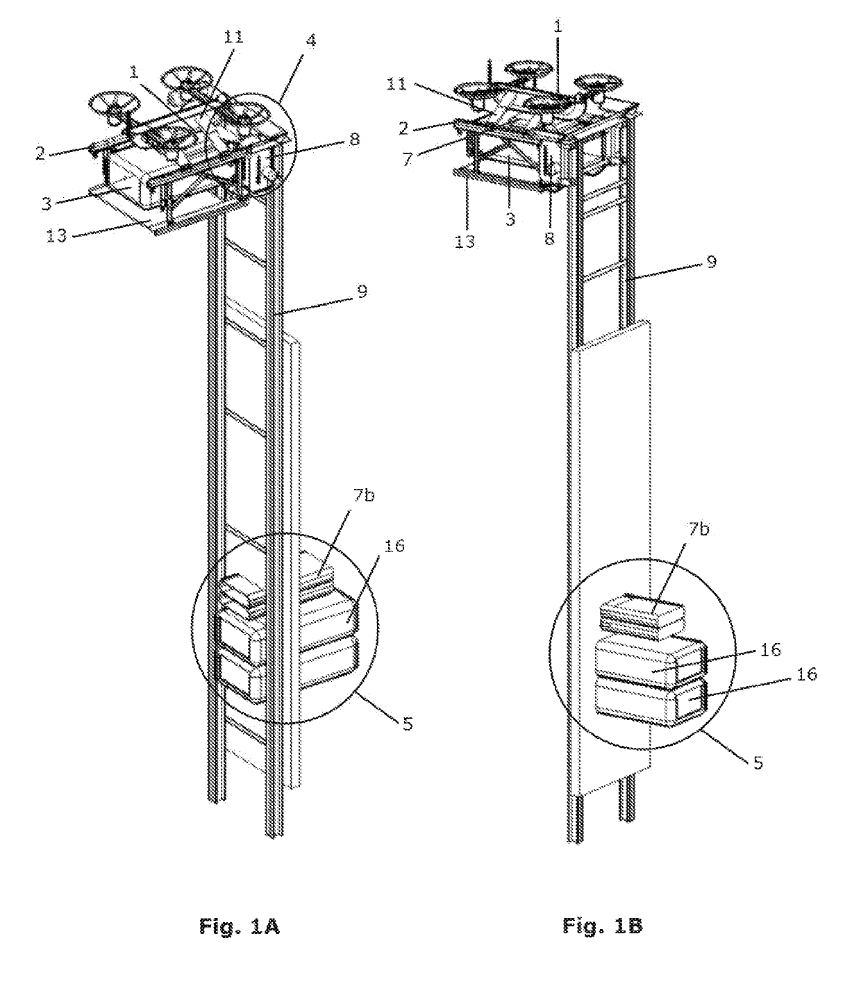
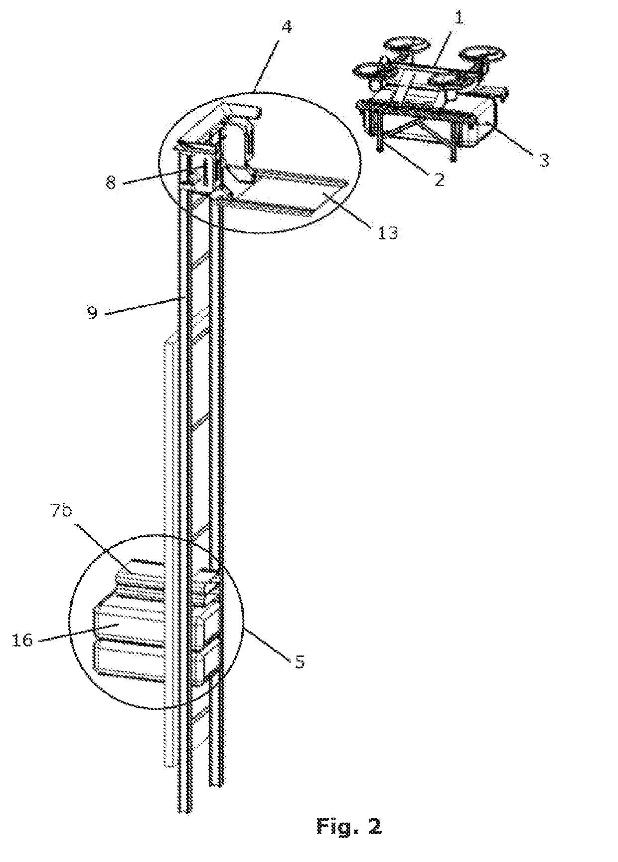
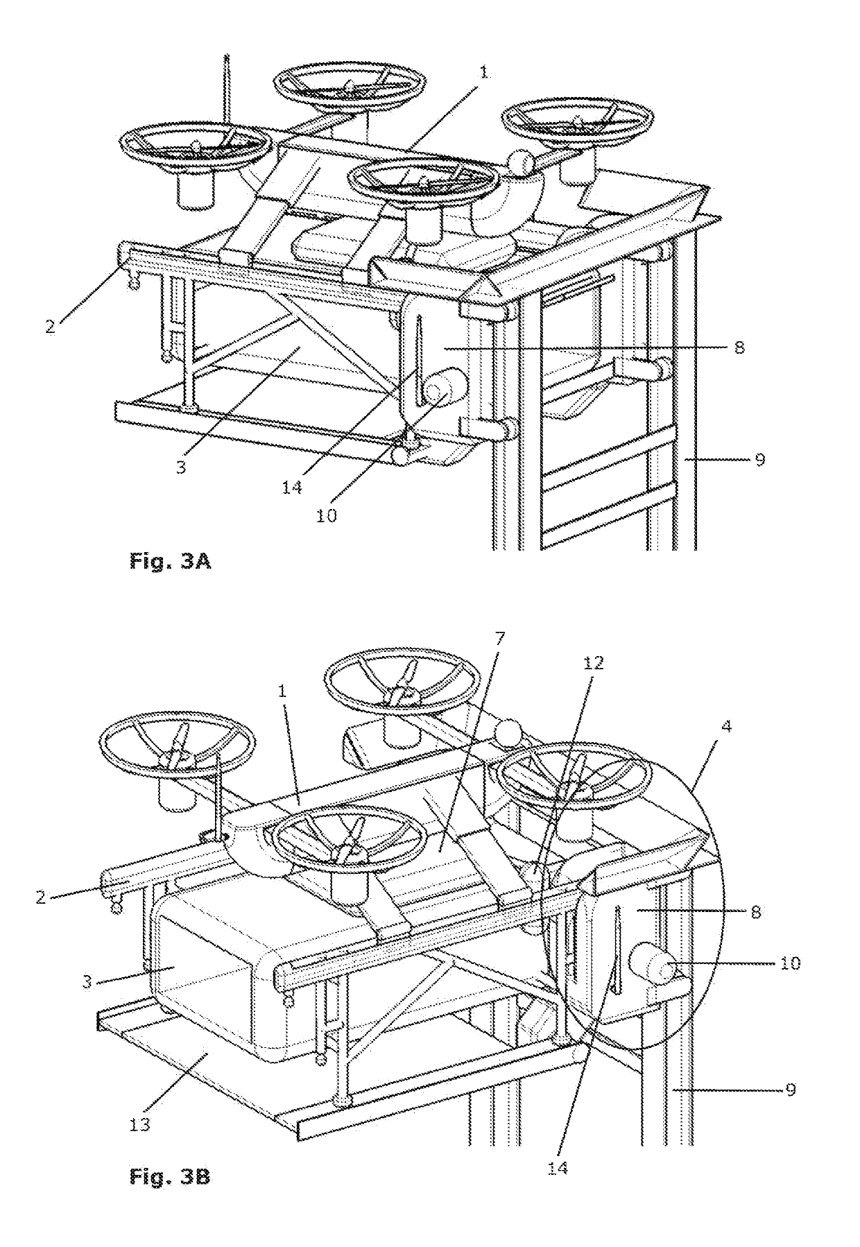
[0195]FIGS. 1A-1B show a deployed home station comprising a docking station (4) and a receiving station (5) which are connected via a transport means (6) which in turn comprises a movable linking means (8) and rails (9) in this embodiment. In the docking station (4), an aerial vehicle (1), preferably a UAV, comprising a frame (2) which holds a cargo module (3), is docked. In the embodiment of the Figures, a platform (13) is comprised in the docking station (4) which platform (13) supports the aerial vehicle (1). Note however that this is an optional feature and the aerial vehicle (1) may be secured to the docking station (4) through other means as well, and preferably is so secured in addition to the platform (13). The Figures furthermore clearly show the frame (2) being connected to the aerial vehicle (1) via a connector mechanism (11). Note that in some embodiments, the connector mechanism (11) allows ...

example 2

hicle (Preferably UAV) with Detachable Cargo Module

[0205]In a second example, the system is different from that of example 1 in that the movable linking means (8) and thus the entire transport means (6) is so adapted to only convey the cargo module (3) between the docking station (4) and the receiving station (5). Obviously this may require some structural changes of the cargo module to allow a secure link between the movable linking means (8) and the cargo module, but the possibilities therein are diverse, ranging from magnetic elements to clamps to male-female connectors or combinations. Additionally, this will require the cargo module to be detachable (and preferably re-attachable) from the aerial vehicle (1) itself (and possibly from a frame (2) of the aerial vehicle (1) which holds the cargo module). The detachment is preferably automated and takes place after a signal of the docking station (4) to the aerial vehicle (1) that the aerial vehicle (1) is correctly docked (and opti...

example 3

hicle (Preferably UAV) with Detachable Frame

[0208]In the third example, the system differs in that the aerial vehicle (1) comprises a frame (2) which holds the cargo module (3), and that said frame (2) is detachable (and preferably re-attachable) from the aerial vehicle (1). The detachment is preferably automated and takes place after a signal of the docking station (4) to the aerial vehicle (1) that the aerial vehicle (1) is correctly docked (and optional further structures are in place to proceed with detachment). Reattachment may then be simply executed in the reversed manner. The movable linking means (8) is adapted to link to said frame (2) and to convey the frame (2) holding the cargo module (3) between docking station (4) and receiving station (5). Again, all previous options remain open, safe that the aerial vehicle (1) stays at the docking station (4) while the frame (2) and cargo module (3) is moved. The receiving station (5) therefore will not need to be modified drastica...


PUM


Abstract

The current invention concerns an improved system for cargo delivery through (unmanned) aerial vehicles (preferably UAVs or drones) to specifically designed home stations. Additionally, a method is described according to which the system of the invention functions.

Description

TECHNICAL FIELD[0001]The invention pertains to the technical field of aerial delivery of cargo and / or passengers at home stations via aerial vehicles, preferably unmanned, and furthermore pertains to an optimized system and method for such deliveries at increased ease and security.BACKGROUND[0002]There remains a need in the art for an improved delivery system that employs (unmanned) aerial vehicles (preferably UAVs) or drones. In such systems, the delivery locations have a docking system or assembly that allows an aerial vehicle to land with a package and transfer said package to the docking system, which then provides it to the user. Most often, such a docking station is placed in a high location so the aerial vehicle may easily reach it without disturbing the surroundings, and with lower danger for the aerial vehicle itself (less obstacles and / or easier to spot the obstacle and adjust course depending thereon). Once the package is transferred, the drone may take off again, while t...

Claims


Application Information

Patent Timeline
Patent Type & Authority Applications(United States)
IPC IPC(8): B64C39/02G06Q10/08B64F1/14B64F1/30
CPCB64C39/024G06Q10/083B64F1/14B64F1/30B64C2201/128B64C2201/141A47G29/14B64D9/00B64U2101/60Y02T10/7072Y02T10/70B64C39/02B64D1/10B64U2201/10
Inventor GOOVAERTS, BART JEAN MARIEPEETERS, IVAN JOS CHRISTINEROTTIERS, KRIS
Owner DRONE FUTURE BVBA
Why Eureka
Try Eureka