
Optical imaging system

a technology of optical imaging and optical imaging module, which is applied in the field of optical imaging system, can solve the problems of difficult use of optical imaging system in small camera module having high performan

Active Publication Date: 2019-05-23
SAMSUNG ELECTRO MECHANICS CO LTD
View PDF3 Cites 1 Cited by
  • Summary
  • Abstract
  • Description
  • Claims
  • Application Information

AI Technical Summary

Benefits of technology

The optical imaging system described in the patent has a high f-number, which makes it difficult for it to be used in a small camera module with high performance.

Problems solved by technology

), such that it may be difficult for the optical imaging system to be used in a small camera module having high performance.

Method used


Image

  • Optical imaging system
  • Optical imaging system
  • Optical imaging system

Examples


Embodiment Construction

[0035]The following detailed description is provided to assist the reader in gaining a comprehensive understanding of the methods, apparatuses, and / or systems described herein. However, various changes, modifications, and equivalents of the methods, apparatuses, and / or systems described herein will be apparent after an understanding of the disclosure of this application. For example, the sequences of operations described herein are merely examples, and are not limited to those set forth herein, but may be changed as will be apparent after an understanding of the disclosure of this application, with the exception of operations necessarily occurring in a certain order. Also, descriptions of features that are known in the art may be omitted for increased clarity and conciseness.

[0036]The features described herein may be embodied in different forms, and are not to be construed as being limited to the examples described herein. Rather, the examples described herein have been provided mer...


PUM


Abstract

An optical imaging system includes a first lens, a second lens, a third lens, a fourth lens, a fifth lens, and a sixth lens sequentially disposed from an object side. The third lens and the sixth lens have positive refractive power, and an f-number (F No.) of the optical imaging system is 1.7 or less.

Description

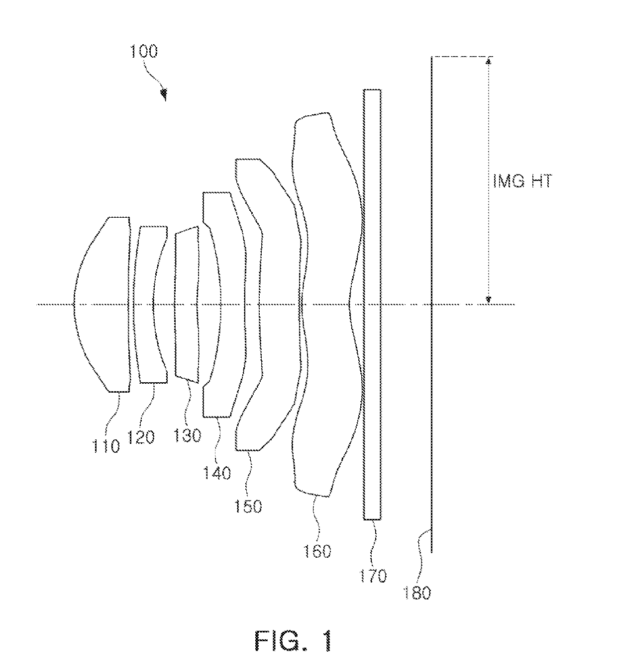
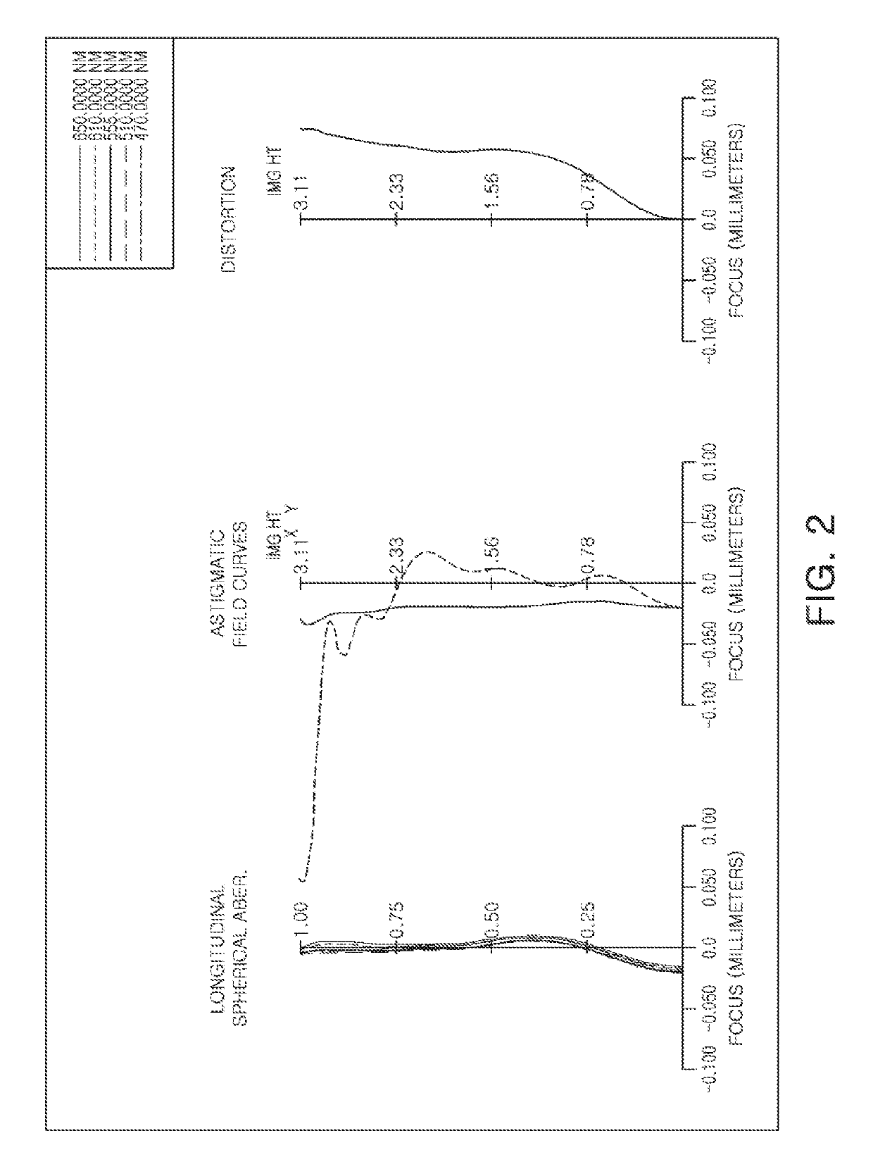
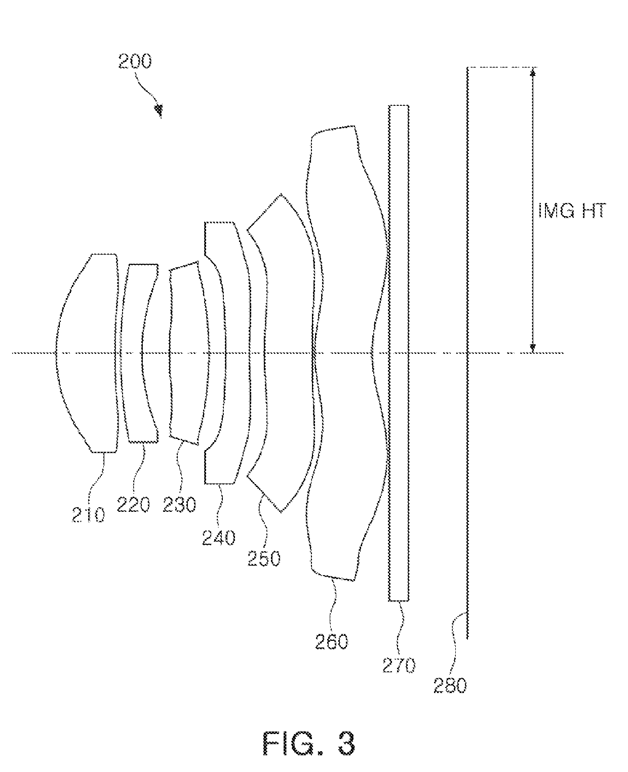
CROSS-REFERENCE TO RELATED APPLICATIONS[0001]This application claims the benefit under 35 USC 119(a) of Korean Patent Application No. 10-2017-0154877 filed on Nov. 20, 2017, in the Korean Intellectual Property Office, the entire disclosure of which is incorporated herein by reference for all purposes.BACKGROUND1. Field[0002]This application relates to an optical imaging system including six lenses.2. Description of the Background[0003]Small camera modules may be mounted in mobile communications terminals. For example, small camera modules may be mounted in thin devices such as mobile phones, or the like. Such small camera modules include an optical imaging system including a small number of lenses so that they may also be thin. For example, the optical imaging system of the small camera module may include four or less lenses.[0004]However, such an optical imaging system may have a high f-number (F No.), such that it may be difficult for the optical imaging system to be used in a sma...

Claims


Application Information

Patent Timeline
IPC IPC(8): G02B9/62G02B13/00G02B27/00
CPCG02B9/62G02B13/0045G02B27/0037G02B13/18
Inventor SON, JU HWANAM, KI JINPARK, JU SUNGJO, YONG JOO
Owner SAMSUNG ELECTRO MECHANICS CO LTD
Learn More