
Time domain aliasing reduction for non-uniform filterbanks which use spectral analysis followed by partial synthesis

a time domain and filterbank technology, applied in the field of time domain aliasing reduction for non-uniform filterbanks which use spectral analysis followed by partial synthesis, can solve the problems of unsuitable coding applications, long transform windows, limited frequency scale designs, etc., to improve the temporal compactness of impulse responses, reduce lapped critically sampled transform frame delay, and no additional redundancy

Active Publication Date: 2019-06-06
FRAUNHOFER GESELLSCHAFT ZUR FOERDERUNG DER ANGEWANDTEN FORSCHUNG EV
View PDF0 Cites 3 Cited by
  • Summary
  • Abstract
  • Description
  • Claims
  • Application Information

AI Technical Summary

Benefits of technology

The present invention adds a post-processing stage to a lapped critically sampled transform (e.g., MDCT) pipeline. This allows for extracting arbitrary frequency scales from the spectrogram with improved temporal compactness of the impulse response, while introducing no additional redundancy and reducing lapped critically sampled transform frame delay.

Problems solved by technology

However, both approaches were designed to involve very long, overlapping transform windows with non-critical sampling or even transforming the entire signal in one step.
These long transform windows and non-critical sampling prohibit precise time-localization in the transform domain and make them unsuitable for coding applications due to a large look ahead and high redundancy.
While allowing direct integration into common lapped MDCT transform pipelines, these Butterfly- and Hadamard-based implementations only allow for very limited frequency scale designs with for example sizes constrained to k=2n with n∈.
Additionally, while some of these methods use MDCT they do not try to reduce the resulting aliasing in the subbands, producing a smeared temporal compactness of the resulting filterbank impulse.

Method used


Image

  • Time domain aliasing reduction for non-uniform filterbanks which use spectral analysis followed by partial synthesis
  • Time domain aliasing reduction for non-uniform filterbanks which use spectral analysis followed by partial synthesis
  • Time domain aliasing reduction for non-uniform filterbanks which use spectral analysis followed by partial synthesis

Examples


Embodiment Construction

[0073]Equal or equivalent elements or elements with equal or equivalent functionality are denoted in the following description by equal or equivalent reference numerals.

[0074]In the following description, a plurality of details are set forth to provide a more thorough explanation of embodiments of the present invention. However, it will be apparent to one skilled in the art that embodiments of the present invention may be practiced without these specific details. In other instances, well-known structures and devices are shown in block diagram form rather than in detail in order to avoid obscuring embodiments of the present invention. In addition, features of the different embodiments described hereinafter may be combined with each other, unless specifically noted otherwise.

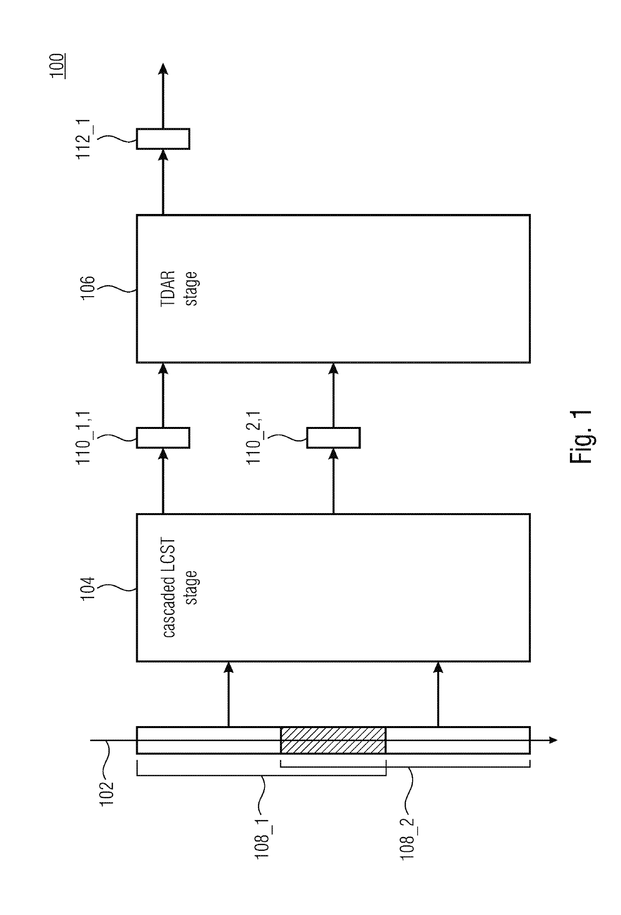
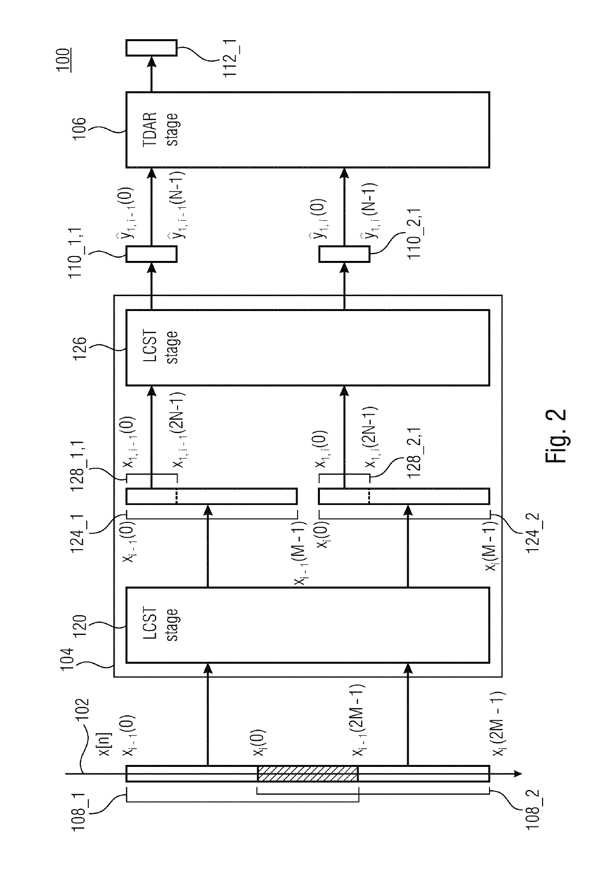
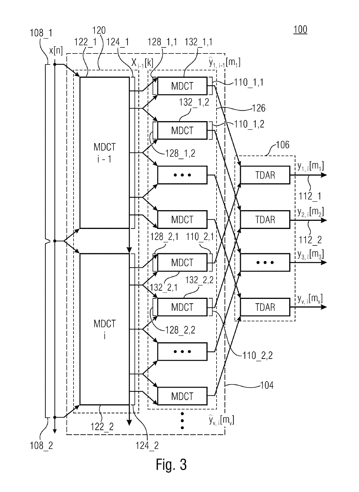
[0075]FIG. 1 shows a schematic block diagram of an audio processor 100 configured to process an audio signal 102 to obtain a subband representation of the audio signal, according to an embodiment. The audio proces...


PUM


Abstract

An audio processor for processing an audio signal to acquire a subband representation thereof includes a cascaded lapped critically sampled transform stage and a time domain aliasing reduction stage, the former being configured to perform a cascaded lapped critically sampled transform on at least two partially overlapping blocks of samples of the audio signal, to acquire a set of subband samples on the basis of a first block of samples of the audio signal, and to acquire a corresponding set of subband samples on the basis of a second block of samples of the audio signal. The latter is configured to perform a weighted combination of two corresponding sets of subband samples, which are acquired on the basis of the first and second blocks of samples of the audio signal, respectively, to acquire an aliasing reduced subband representation of the audio signal.

Description

CROSS-REFERENCE TO RELATED APPLICATIONS[0001]This application is a continuation of copending International Application No. PCT / EP2017 / 068932, filed Jul. 26, 2017, which is incorporated herein by reference in its entirety, and additionally claims priority from European Application No. EP 16181883.6, filed Jul. 29, 2016, which is incorporated herein by reference in its entirety.BACKGROUND OF THE INVENTION[0002]Embodiments relate to an audio processor / method for processing an audio signal to obtain a subband representation of the audio signal. Further embodiments relate to an audio processor / method for processing a subband representation of an audio signal to obtain the audio signal. Some embodiments relate to time domain aliasing reduction in subbands of non-uniform orthogonal filterbanks based on MDCT (MDCT=modified discrete cosine transform) analysis / synthesis, e.g., in subbands of non-uniform orthogonal MDCT filterbanks.[0003]MDCT is widely used in audio coding applications due to ...

Claims


Application Information

Patent Timeline
IPC IPC(8): G10L19/02G10L19/022G06F17/14
CPCG10L19/0204G10L19/0212G10L19/022G06F17/147G10L19/167G06F17/14G10L19/02
Inventor WERNER, NILSEDLER, BERND
Owner FRAUNHOFER GESELLSCHAFT ZUR FOERDERUNG DER ANGEWANDTEN FORSCHUNG EV
Learn More