Ice Pack and Ice Pack Grid System

a grid system and grid technology, applied in the field of ice packs, can solve the problem that existing ice packs do not have specific shapes that allow

Inactive Publication Date: 2019-06-13
9352 1425 QUEBEC INC
View PDF0 Cites 7 Cited by
  • Summary
  • Abstract
  • Description
  • Claims
  • Application Information

AI Technical Summary

Problems solved by technology

Existing ice packs do not have specific shapes that allow th...

Method used


Image

  • Ice Pack and Ice Pack Grid System
  • Ice Pack and Ice Pack Grid System
  • Ice Pack and Ice Pack Grid System

Examples


Embodiment Construction

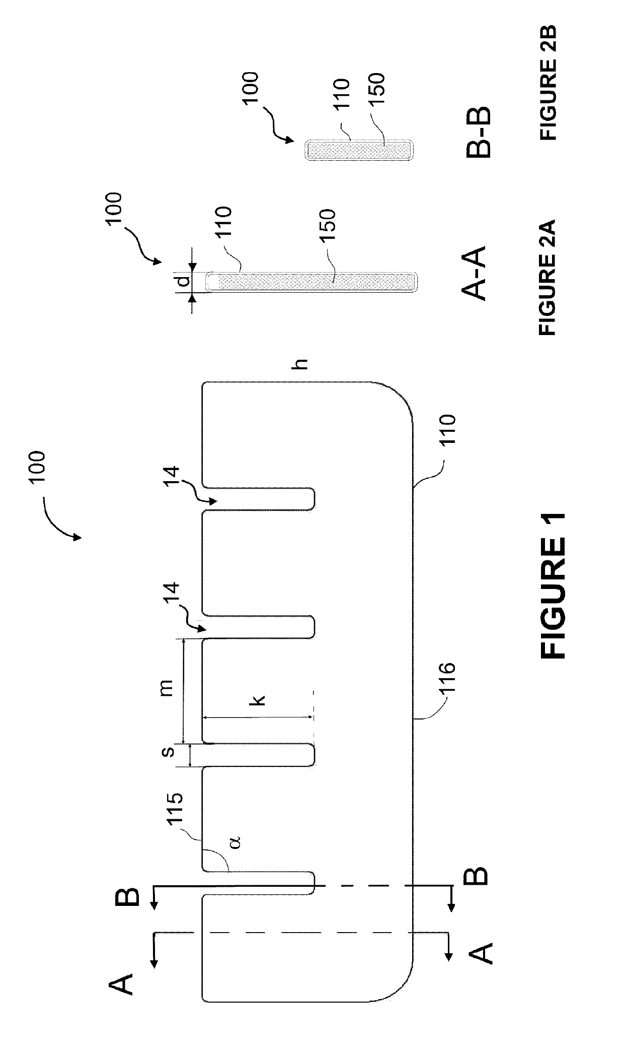
[0039]A novel ice pack and ice pack grid system will be described hereinafter. Although the invention is described in terms of specific illustrative embodiments, it is to be understood that the embodiments described herein are by way of example only and that the scope of the invention is not intended to be limited thereby.

[0040]Coolers along with ice packs are typically used in order to transport or to temporary store objects in an environment with temperature lower than the temperature outside of the cooler. The ice packs are typically dropped down the cooler or positioned on either side of the cooler and then multiple objects to be cooled are thrown into the cooler to form a pile.

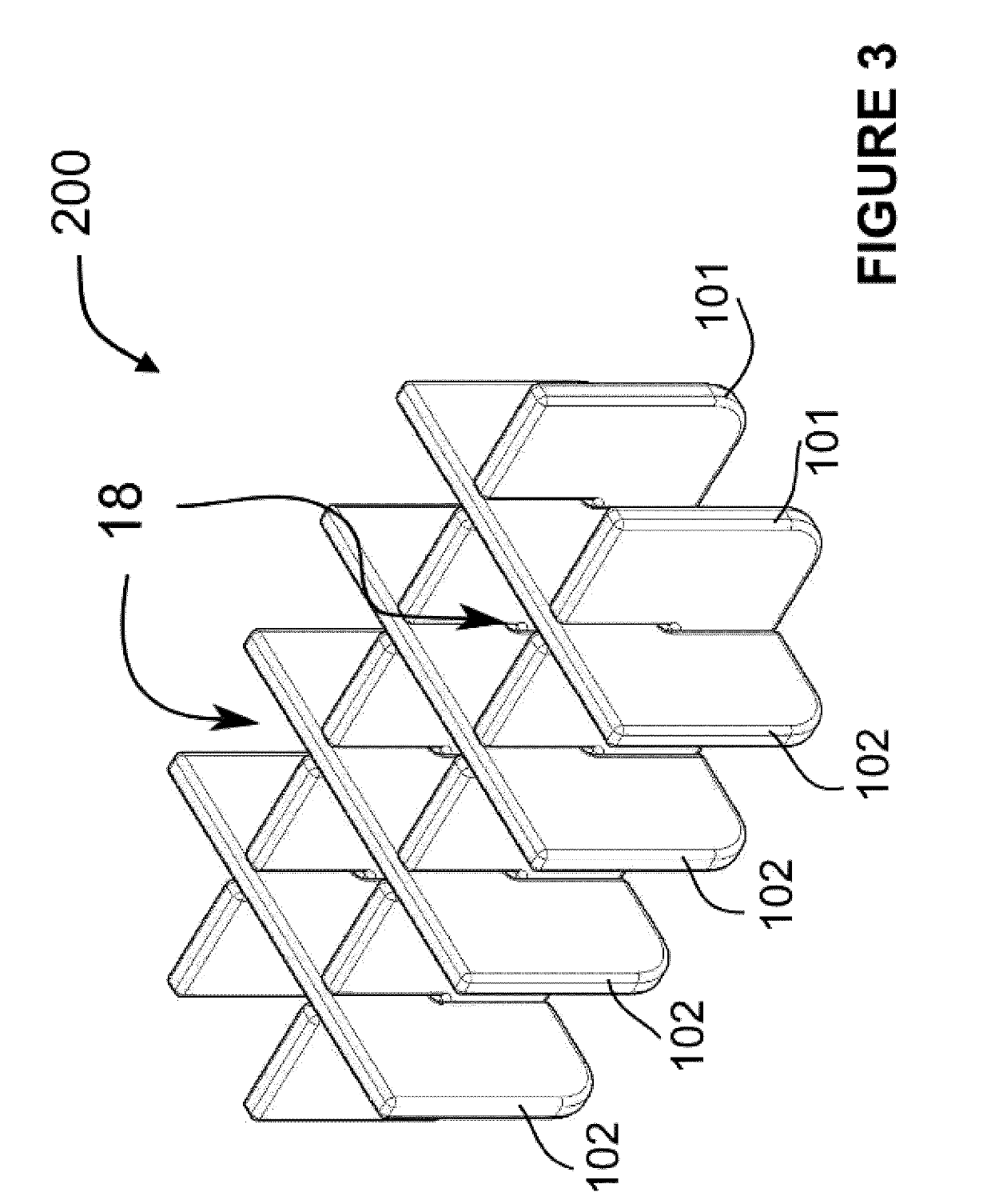
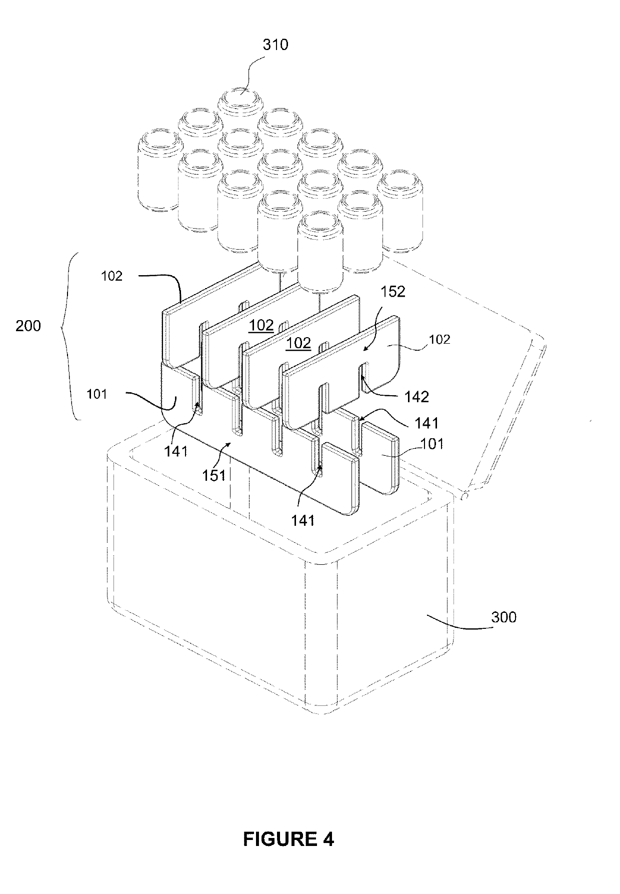
[0041]Such messy arrangement of the objects to be cooled does not lead to equal distribution of temperature in the cooler and the objects that are located closer to the ice packs are usually colder than the ones that are stored in the middle of the pile.

[0042]The ice packs and the ice pack grid system as ...


PUM


Abstract

An ice pack generally shaped as a rectangular cuboid is provided. The ice pack has a first face and a second face which are parallel to each other, each face comprising attachment means adapted to be removably attached to the face of another ice pack generally shaped as a 5 rectangular cuboid, configured to create a grid forming a plurality of open spaces. An ice pack grid system for a plurality of items is also provided. The system has a plurality of ice packs of different lengths, each ice pack having at least one slit running substantially halfway across the ice pack's width, and each ice pack being sized so that the slit can straddle the width of another ice pack and thus interlock in a perpendicular configuration so as to create a grid 0 pattern forming a plurality of spaces to receive items to be cooled.

Description

CROSS-REFERENCE TO RELATED APPLICATIONS[0001]The present patent application claims the benefits of priority of commonly assigned UK Patent Application No. GB 1606301.8, entitled “ICE PACK GRID SYSTEM” and filed at the UK Intellectual Property Office on Apr. 12, 2016.FIELD OF THE INVENTION[0002]The present invention generally relates to ice packs and more particularly to an ice pack grid system.BACKGROUND OF THE INVENTION[0003]Ice packs have been in use for decades. Some are hollow plastic containers that can be filled with tap water and then to be frozen in a freezer, prior to their use in a cooler. Other ice packs contain a high density liquid which can keep cool for an extended period of time. The latter type of ice pack is sealed and its liquid is prevented from leaking. Existing ice packs do not have specific shapes that allow them to be easily combined or to be held in a specific configuration.SUMMARY OF THE INVENTION[0004]The aforesaid and other objectives of the present inven...

Claims


Application Information

Patent Timeline
IPC IPC(8): B65D81/18B65D5/49B65D5/32
CPCB65D81/18B65D5/48038B65D5/4803B65D5/32F25D3/08B65D25/04B60N3/102B65D85/72F25D31/007F25D2303/08222F25D2331/809
Inventor COULOMBE, YANNICKDEMERS, MATHIEU
Owner 9352 1425 QUEBEC INC
Why Eureka
Try Eureka