
Dental suturing needle

Inactive Publication Date: 2019-06-20
HANMAUM CO LTD
View PDF2 Cites 0 Cited by
  • Summary
  • Abstract
  • Description
  • Claims
  • Application Information

AI Technical Summary

Benefits of technology

[0012]As apparent from the fore-going, the present invention advantageously provides a three-dimensional suturing needle having a structure wherein the needle part is curved at a predetermined angle in a lateral direction two to three times from the eye part, thereby facilitating securement of a suturing sp

Problems solved by technology

However, when the conventional medical suturing needle is used inside the mouth cavity or a limited space, it is inconvenient to approach an area to be treated and excessive force is inconveniently applied to the hand or wrist due to difficulties in securing a suturing space because the needle part 2 and the eye part 3 of

Method used


Image

  • Dental suturing needle
  • Dental suturing needle

Examples


Example

BEST MODE

[0017]Now, preferred embodiment to accomplish the aforementioned purposes and effects of the present invention will be described in more detail.

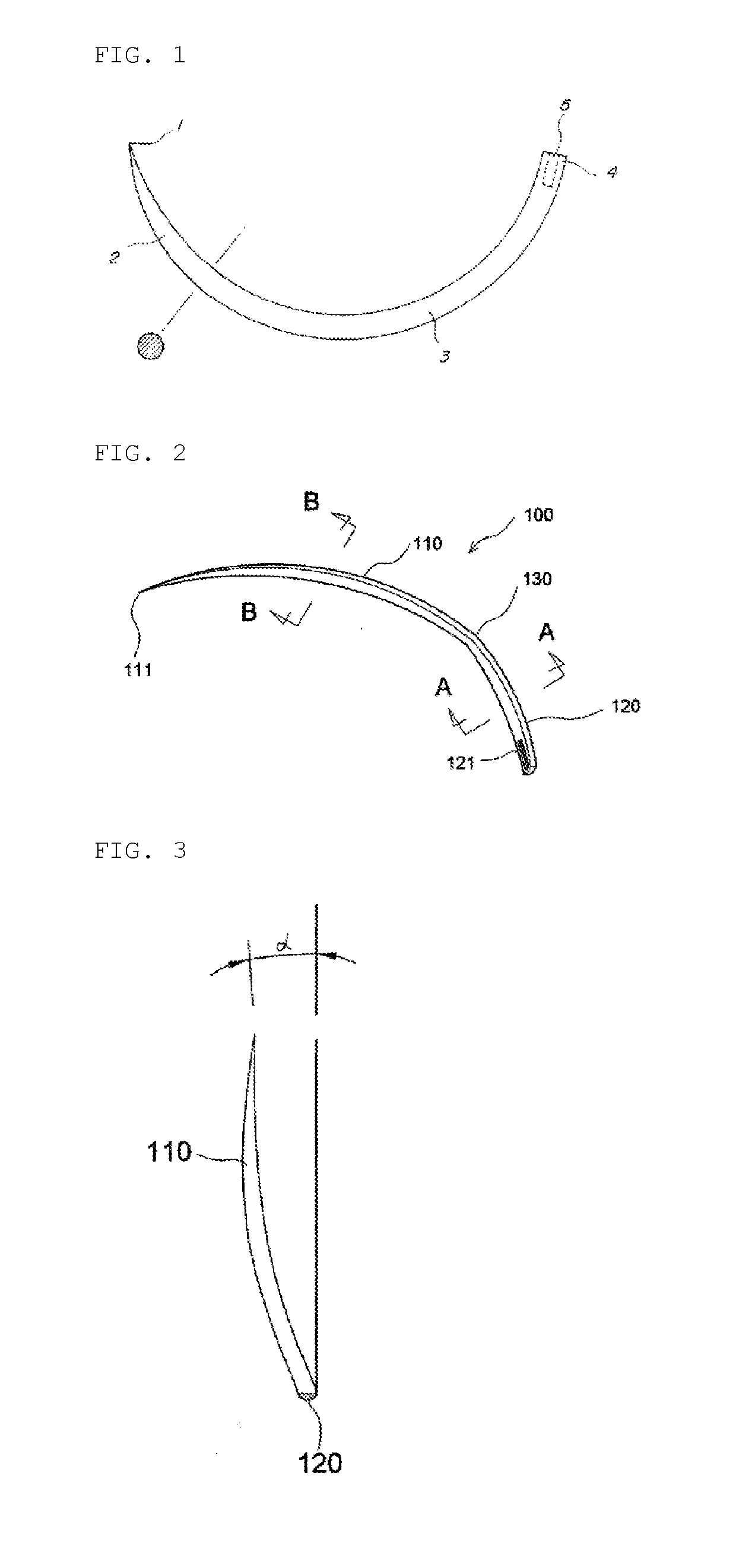
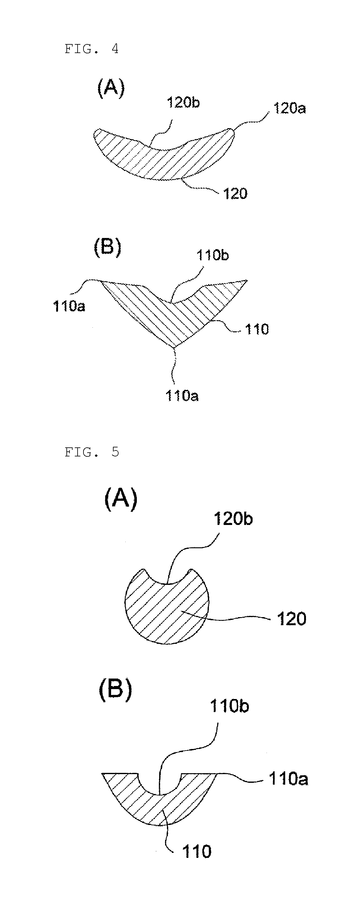
[0018]A dental suturing needle 100 according to the present invention includes a needle part 110 provided with a needle point 111; and an eye part 120 continuously extending from the needle part 110 and provided with a needle eye 121, wherein a curved part 130 is provided between the needle part 110 and the eye part 120 and configured such that the needle part 110 is inclined at an angle of 20 to 45° to the left or right with respect to the eye part 120.

[0019]The curved part 130 is formed at a point ⅓ or 3 / 10 from the needle point 111 or the needle eye 121. The needle point 111 is formed so as to have an inclination (α) of 20 to 45° in a lateral direction (left or right side) with respect to the eye part 120, as illustrated in FIG. 3.

[0020]Here, the inclination (α) is preferably 30° to 45°. Since this inclination (α) is an angel pro...


PUM


Abstract

The present invention provides a dental suturing needle comprising a needle part provided with a needle point, and an eye part extending from the needle part and provided with an eye of the needle, wherein between the needle part and eye part is a curved part which is structured so that the needle part slants to the left or right by 20-45° with respect to the eye part. The present invention provides a three-dimensional suturing needle structured so that the needle part curves laterally by a set angle two to three times from the eye part to thus facilitate securing suturing space inside the mouth cavity, remove discomfort to the hand due to easy access to the treatment area, and allow smooth suturing without having to apply excessive pressure to the wrist, and additionally, the present invention is a very useful invention which creates spaces that do not come into contact with tissues to thus allow smooth movement of the suturing needle and minimize damage to the tissues.

Description

TECHNICAL FIELD[0001]The present invention relates to a dental suturing needle, and more particularly to a three-dimensional suturing needle having a structure wherein the needle part is curved at a predetermined angle in a lateral direction two to three times from the eye part, thereby facilitating securement of a suturing space inside the mouth cavity, allowing easy suturing without stressing the hand and without imposing excessive force on the wrist due to easy access to an area to be treated.BACKGROUND ART[0002]As examples of a medical suturing needle used for sealing the living tissue, there are a circular needle with a structure wherein a cross-sectional shape of a part extending from a needle point part to a body part is circular and a cross section of the body part has a circular, triangular, square, or sharp plate shape; and an angular needle with a polygonal shape, such as a triangle, including cutting edges that are formed on a plurality of ridge lines.[0003]An angular ne...

Claims


Application Information

Patent Timeline
IPC IPC(8): A61B17/06A61C3/00
CPCA61B17/06066A61C3/00A61B2017/06085A61B2017/06028A61B2017/06019A61B2017/06071A61B17/06
Inventor KIM, NAM GYOU
Owner HANMAUM CO LTD
Learn More