Single sprocket

Active Publication Date: 2019-06-27
SRAM
View PDF0 Cites 0 Cited by
  • Summary
  • Abstract
  • Description
  • Claims
  • Application Information

AI Technical Summary

Problems solved by technology

However, this state is not produced for every pinion of the multiple pinion arrangement.
However, this advantage in terms of stability is opposed by relatively large chain tensile forces which may arise as a result of the changed transmission ratio between maintained crank length and reduced sprocket diameter.
In the event of insufficient rigidity of the sprock

Method used


Image

  • Single sprocket
  • Single sprocket
  • Single sprocket

Examples


Example

DETAILED DESCRIPTION OF THE DRAWINGS

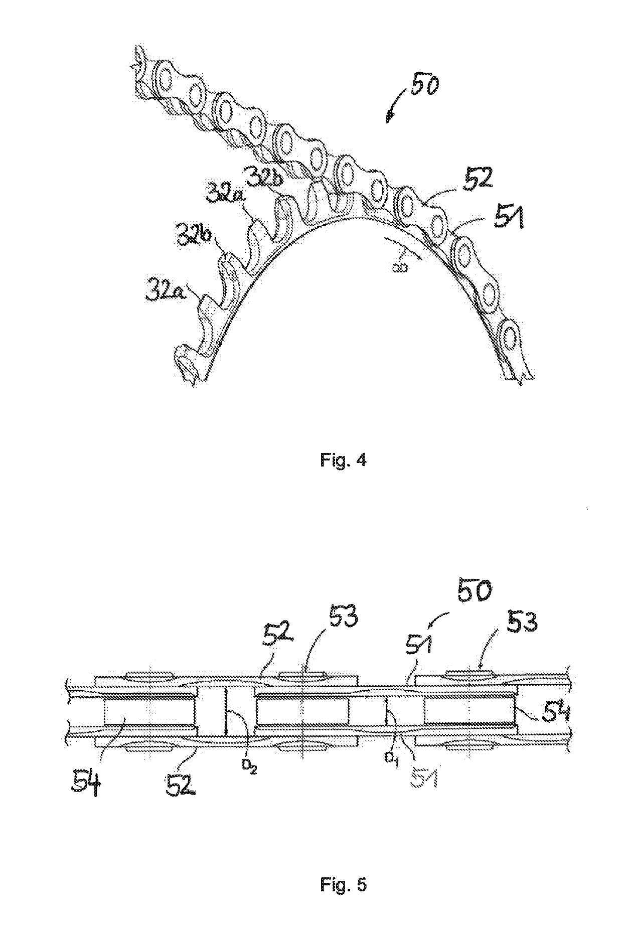
[0033]In the design of the chain rings, it is important to to take into consideration the increased stability requirements and secondly the requirements for light weight which now exist. The selection of material (weight and strength) and also the geometry (rigidity) are of importance here.

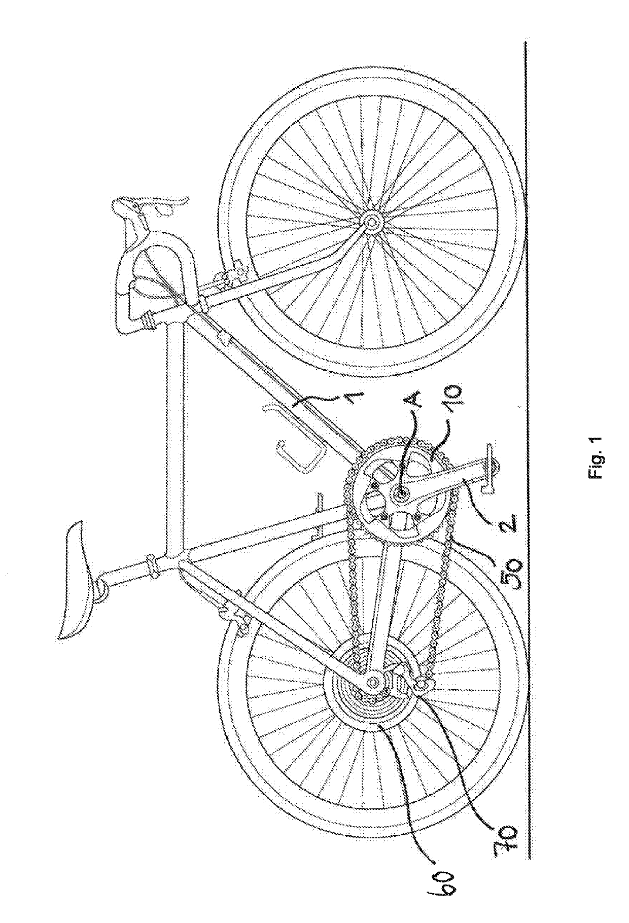
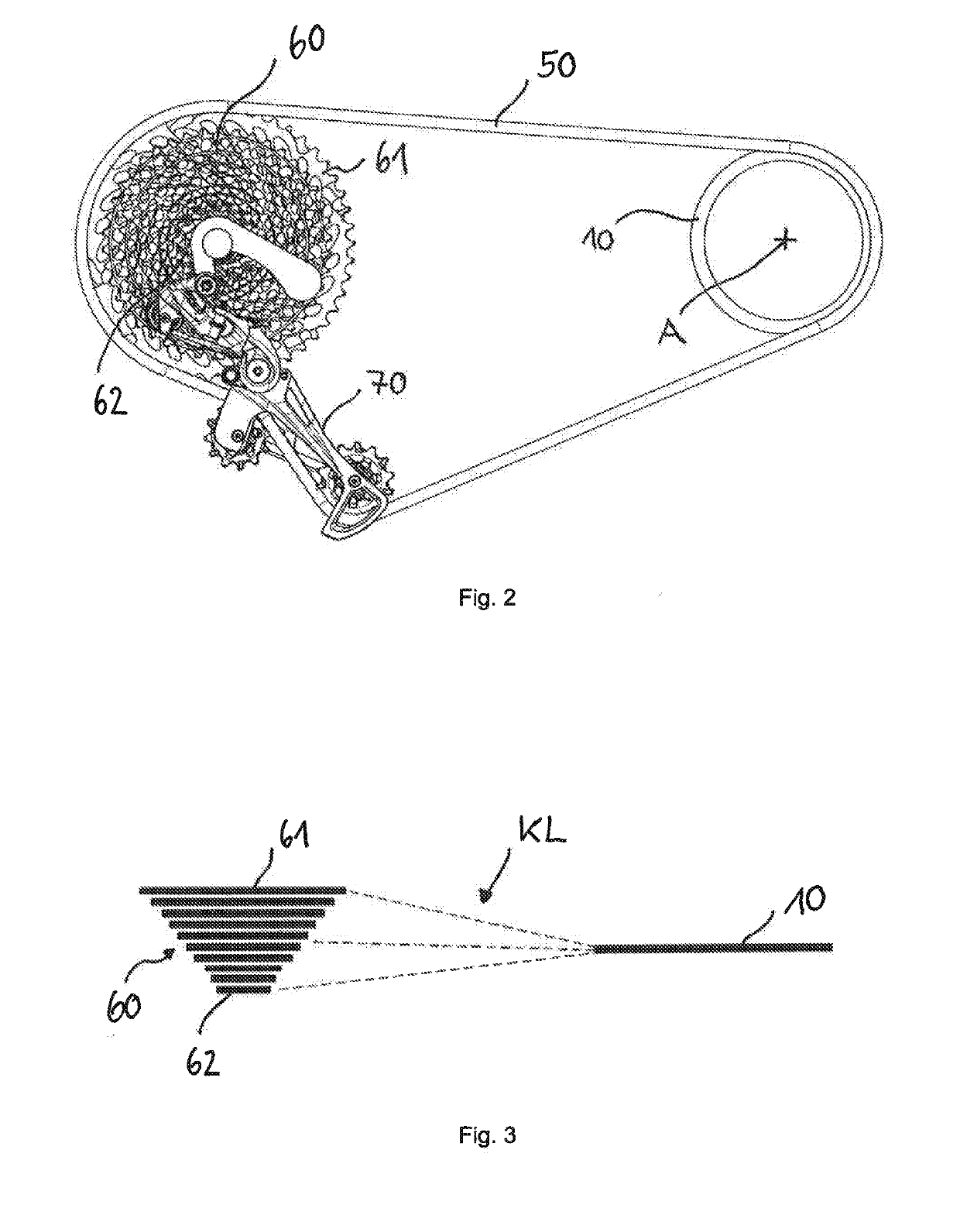
[0034]At the teeth of the sprocket in the tooth center plane, the chain tensile force is introduced into the teeth, wherein the direction of the chain tensile force on account of the chain skew with respect to a rear pinion of a multiple pinion set is not parallel to the tooth center plane.

[0035]Firstly, the tooth center plane of the sprocket is intended to be arranged as centrally as possible with respect to the multiple pinion set in order to restrict the chain skew. Secondly, the hub region of the sprocket cannot be freely varied because of predetermined frame and crank connection extents. This leads to the sprocket having an offset in the axial direction bet...


PUM


Abstract

A single sprocket for mounting on a pedal crank of a bicycle is provided. The sprocket h is mounted rotatably about an axis of rotation of a bicycle, and for engaging in a bicycle chain with chain inner link plate pairs and chain outer link plate pairs. The sprocket includes an axial outer side, an axial inner side, a hub region, a tooth region and a connecting region. A tooth center plane of the sprocket is offset inwards in the axial direction with respect to a hub center plane.

Description

[0001]This application claims priority to, and / or the benefit of, German patent application DE 10 2017 012 035.8, filed on Dec. 22, 2017, the contents of which are herein referenced in their entirety.FIELD OF THE INVENTION[0002]The invention relates to a single sprocket drive system, and specifically to a single sprocket drive system for a bicycle.BACKGROUND[0003]Chain drives in bicycles already have a long development history. In accordance with changing requirements, different requirements will have to be met again.[0004]The starting point was an input chain drive with a single sprocket (front sprocket) on the pedal crank in combination with a single pinion (rear sprocket) on the hub on the rear wheel, wherein front and rear sprockets were coupled by means of a roller-type chain.[0005]This concept has basically been retained in the case of multi-speed drives having change-over devices for transferring the roller-type chain (front derailleur and rear gear shift mechanism) between a...

Claims


Application Information

Patent Timeline
IPC IPC(8): F16H55/30B62M9/10
CPCF16H55/30B62M9/105B62M9/00B62M9/04B62M9/02
Inventor HANKE, JOACHIM
Owner SRAM
Why Eureka
Try Eureka