Bicycle chainring

a chainring and bicycle technology, applied in the field of bicycle chainrings, to achieve the effect of reducing weight and improving appearan

Inactive Publication Date: 2010-03-30
SHIMANO INC
View PDF18 Cites 76 Cited by
  • Summary
  • Abstract
  • Description
  • Claims
  • Application Information

AI Technical Summary

Benefits of technology

[0007]One object of the present invention is to provide a bicycle chainring gear with a reduced weight and improved appearance.
[0008]Another object of the present invention is to provide bicycle chainring gear that has a reduction in transmission of noise when riding, making the ride smoother and quieter.

Problems solved by technology

However, even with recent improvements in material science, the chain engaging gears contribute a measurable amount of weight to the bicycle.

Method used


Image

  • Bicycle chainring
  • Bicycle chainring
  • Bicycle chainring

Examples


second embodiment

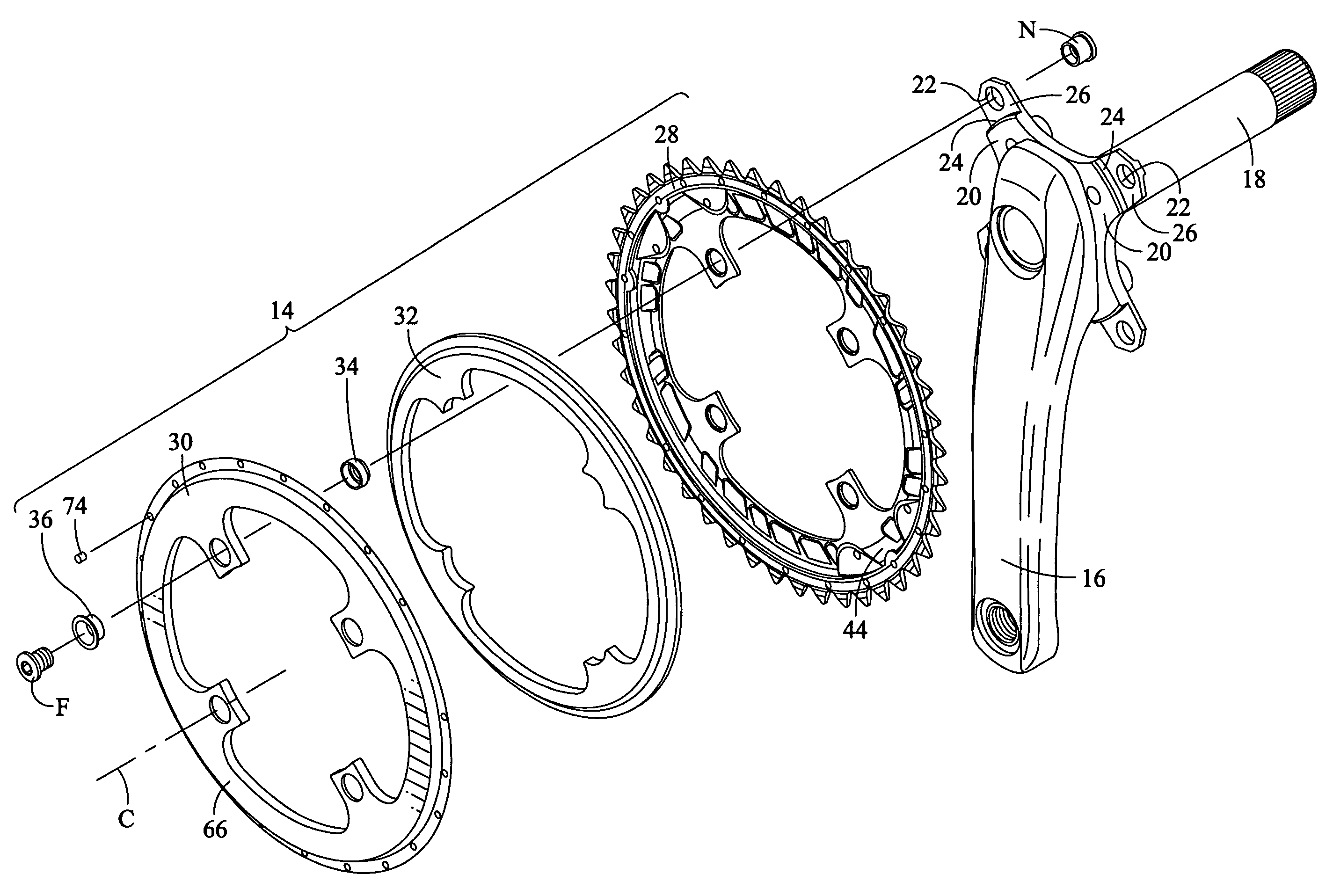
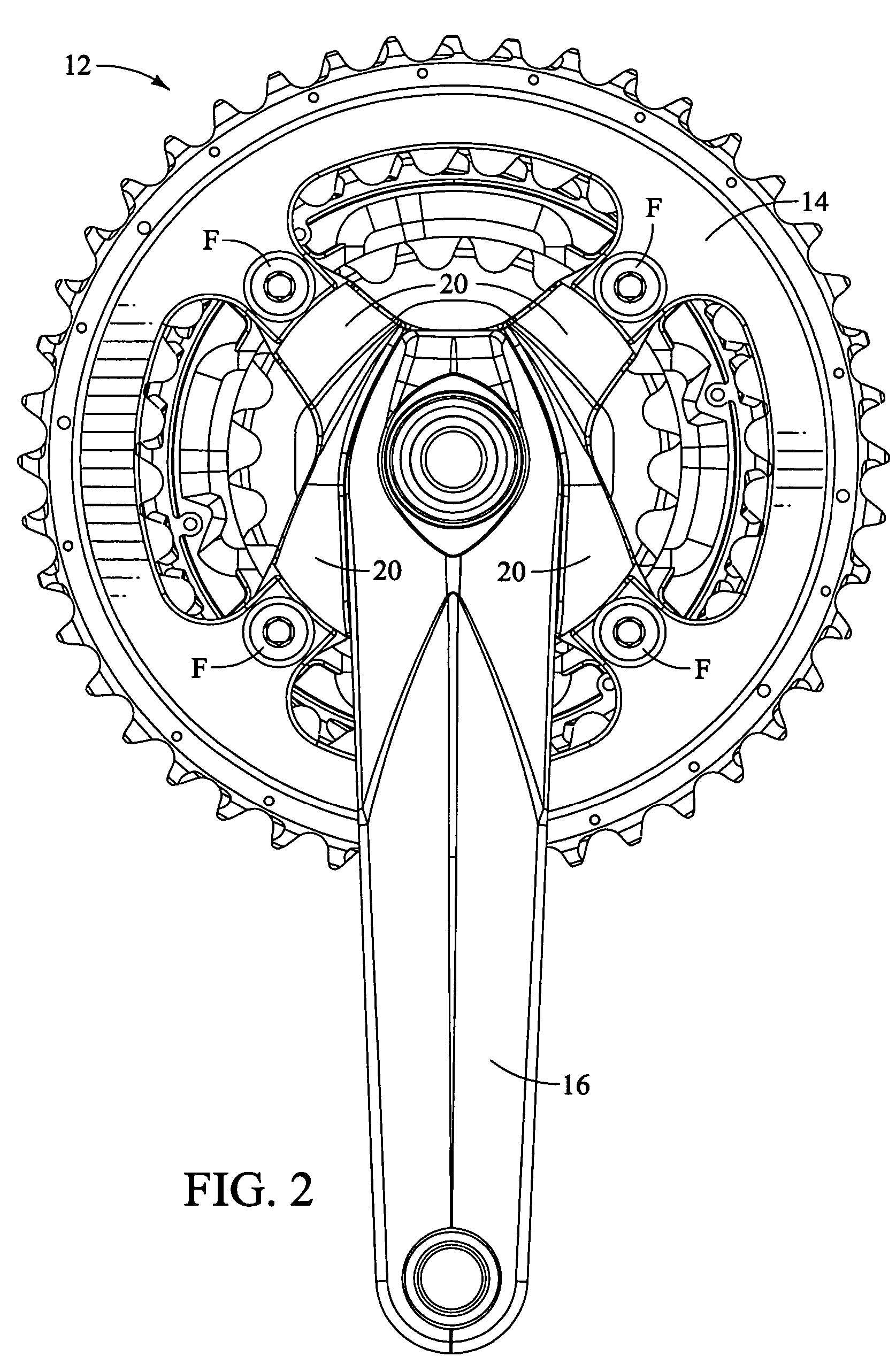
[0072]Referring now to FIGS. 21, 22 and 23, a crank assembly 112 that includes a bicycle chainring 114 in accordance with a second embodiment of the present invention will now be explained. In view of the similarity between the first and second embodiments, the parts of the second embodiment that are identical to the parts of the first embodiment will be given the same reference numerals as the parts of the first embodiment. Moreover, the descriptions of the parts of the second embodiment that are identical to the parts of the first embodiment may be omitted for the sake of brevity. The parts of the second embodiment that differ slightly from the parts of the first embodiment will be indicated with a single prime (′) or will be provided with a new reference numeral.

[0073]The crank assembly 112 is generally configured for use with a bicycle that only includes a single gear element at the front portion of the drive train of the bicycle. Specifically, the crank assembly 112 includes th...

third embodiment

[0083]Referring now to FIGS. 24, 25, 26 and 27, a bicycle chainring 214 in accordance with a third embodiment of the present invention will now be explained. In view of the similarity between the first, second and third embodiments, the parts of the third embodiment that are identical to the parts of the first or second embodiments will be given the same reference numerals as the parts of the first or second embodiments. Moreover, the descriptions of the parts of the third embodiment that are identical to the parts of the first or second embodiment may be omitted for the sake of brevity.

[0084]The bicycle chainring 214 basically includes a first member 228 and a second member 230. The first member 228 includes a plurality of radially inward extending parts 50′ (although only one is shown), a plurality of spaced apart gear teeth 258, recesses 260 and an axially extending wall 70′. Each of the radially inward extending parts 50′ is formed with a chainring attachment opening 52 that is ...

fourth embodiment

[0088]Referring now to FIGS. 28, 29, 30 and 31, a bicycle chainring 314 in accordance with a fourth embodiment of the present invention will now be explained. In view of the similarity between the first and fourth embodiments, the parts of the fourth embodiment that are identical to the parts of the first embodiment will be given the same reference numerals as the parts of the first embodiment. Moreover, the descriptions of the parts of the fourth embodiment that are identical to the parts of the first embodiment may be omitted for the sake of brevity.

[0089]The bicycle chainring 314 basically includes a first member 328 and a second member 330. The first member 328 is formed with a plurality of gear teeth 58, a plurality of fastening apertures 59″ and an annular axially extending wall 70″.

[0090]The second member 330 is formed with a plurality of fastening apertures 72″ and a plurality of radially inward extending parts 64″ that include chainring attachment openings 67″.

[0091]The fir...


PUM


Abstract

A bicycle chainring is formed from a first member and an second member. The first member includes a center rotational axis, a crank attachment portion with a plurality of chainring attachment openings and an annular tooth portion with a plurality of chain engaging gear teeth. The second member disposed around the center rotational axis and is fixedly attached to overlie at least one of the crank attachment portion and the annular tooth portion to reinforce the first member without obstructing access to the chainring attachment openings.

Description

BACKGROUND OF THE INVENTION[0001]1. Field of the Invention[0002]This invention generally relates to a bicycle chainring. More specifically, the present invention relates to a bicycle chainwheel that is made of at least two attached annular portions.[0003]2. Background Information[0004]Bicycling is becoming an increasingly more popular form of recreation as well as a means of transportation. Moreover, bicycling has become a very popular competitive sport for both amateurs and professionals. Whether the bicycle is used for recreation, transportation or competition, the bicycle industry is constantly improving the various components of the bicycle. One set of components that have been extensively redesigned is the bicycle power transmission gears.[0005]Specifically, the chain engaging gears of the bicycle have been re-shaped to reduce friction and have been made more light weight to reduce the total mass of the bicycle. However, even with recent improvements in material science, the ch...

Claims


Application Information

Patent Timeline
Patent Type & Authority Patents(United States)
IPC IPC(8): F16H55/30
CPCB62M9/105
Inventor TABE, KOSHIYAMANAKA, MASAHIROTETSUKA, TOSHIOSHIRAISHI, SHINGOINOUE, HIDEYANISHIMOTO, YUSUKEEMURA, ATSUHIRO
Owner SHIMANO INC
Why Eureka
Try Eureka