
Ordering of csi in uci

a technology of csi and uci, applied in the field of csi order, can solve the problems of large payload size of aggregated uci, large payload variation, and general less accurate csi than aperiodic csi on pusch, and achieve the effect of reducing the loss of csi at the gnb

Active Publication Date: 2019-06-27
TELEFON AB LM ERICSSON (PUBL)
View PDF0 Cites 50 Cited by
  • Summary
  • Abstract
  • Description
  • Claims
  • Application Information

AI Technical Summary

Benefits of technology

The patent text is describing a technique to improve the performance of wireless networks by reducing the loss of information when data is transmitted between devices. This is achieved by omitting certain parts of the data, which allows the receiving device to estimate the missing data based on the available information. This technique minimizes the impact on the network and ensures efficient data transmission.

Problems solved by technology

The aggregated UCI payload size thus can be quite large.
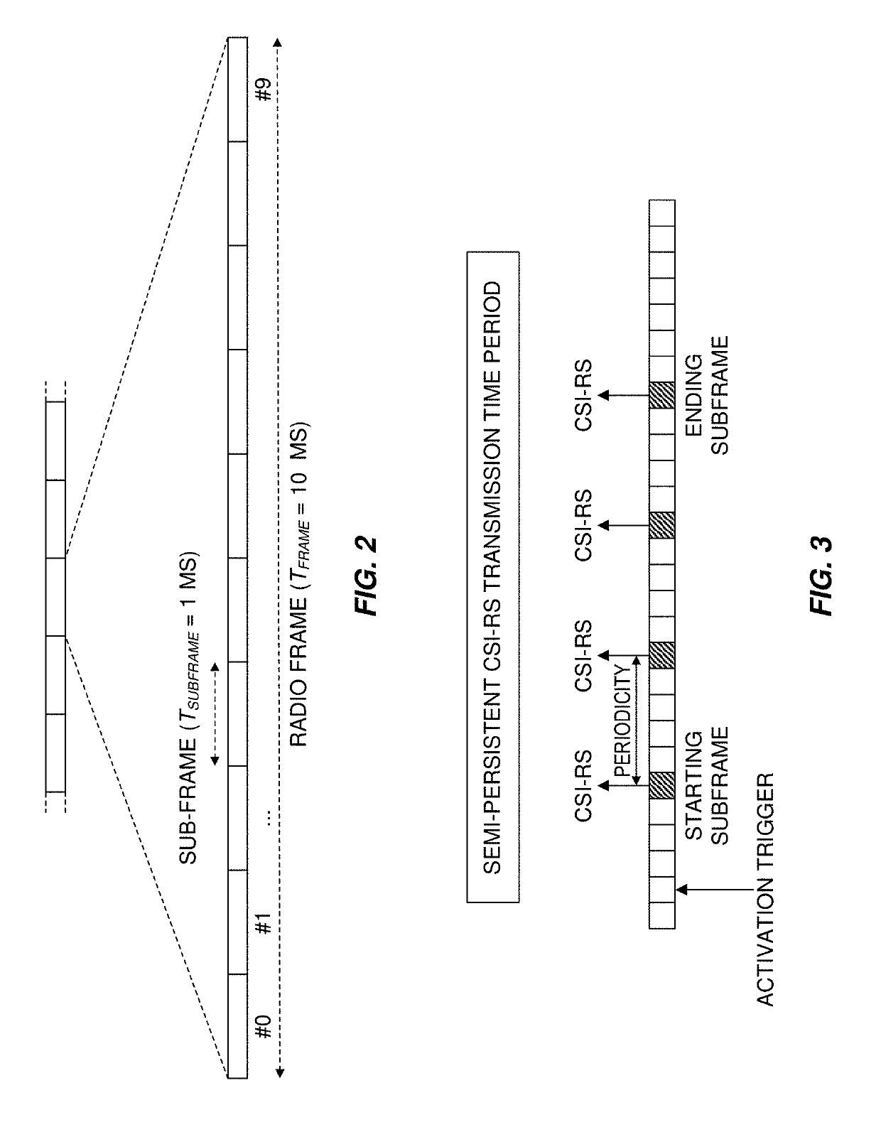
However, unlike periodic CSI-RS, dynamic signaling is needed to activate and possibly deactivate the CSI-RS transmission.
However, periodic CSI reports are formed such that they fit in the small payload of PUCCH, and so may carry less information even when they are piggy backed on PUSCH, for example by the use of codebook subsampling.
Furthermore, periodic CSI reporting in LTE requires that at least one PUCCH resource be configured for the UE, which is a waste of PUCCH resources which are reserved and may be unused even if the periodic CSI is always carried on PUSCH.
Therefore, while LTE can transmit periodic CSI on PUSCH with semi-persistent resource allocation, such CSI is generally less accurate than aperiodic CSI on PUSCH
One issue with Type II CSI reporting is that the payload can vary drastically depending on if the UE selects RI=1 or RI=2 (as is illustrated in Table 1).
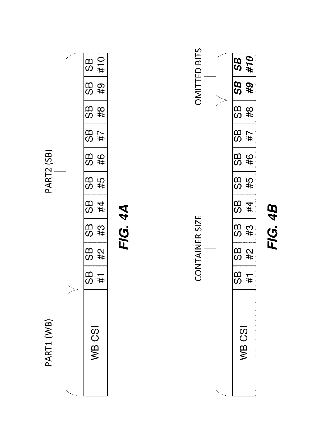
As the gNB is unaware of the selected RI when allocating the PUSCH resources, it could potentially allocate a too small resource so that the CSI payload will not fit.
FIG. 4B depicts an example scenario where a gNB has allocated insufficient resources for the CSI payload, i.e., the container size is too small to hold all of the Part 2 data, resulting in the omission of certain CSI bits.
The agreed-upon mechanism for CSI omission raises certain challenges, however.
These issues have not yet been addressed.

Method used


Image

  • Ordering of csi in uci
  • Ordering of csi in uci
  • Ordering of csi in uci

Examples


embodiments

Group C Embodiments

[0224]18. A wireless device for reporting Channel State Information (CSI), the wireless device comprising: processing circuitry configured to perform any of the steps of any of the Group A or O embodiments; and power supply circuitry configured to supply power to the wireless device.

[0225]19. A user equipment (UE) for reporting Channel State Information (CSI), the UE comprising: an antenna configured to send and receive wireless signals; radio front-end circuitry connected to the antenna and to processing circuitry, and configured to condition signals communicated between the antenna and the processing circuitry; the processing circuitry being configured to perform any of the steps of any of the Group A or O embodiments; an input interface connected to the processing circuitry and configured to allow input of information into the UE to be processed by the processing circuitry; an output interface connected to the processing circuitry and configured to output infor...


PUM


Abstract

Methods and systems for reporting Channel State Information (CSI), including ordering of CSI in Uplink Control Information (UCI), are provided herein. According to one embodiment, a method performed in a wireless device for reporting CSI comprises at least one of: receiving an indication of a resource allocation for an UL transmission; determining, from the indication, a maximum container size for a CSI report; mapping the one or more information bits of a CSI report to a bitstream, optionally such that a first CSI subset is mapped to more significant bits than a second CSI subset; and omitting the one or more least significant bits of the bitstream.

Description

TECHNICAL FIELD[0001]Channel State Information (CSI) feedback / reporting, New Radio (NR), Semi-Persistent Scheduling (SPS)INTRODUCTION[0002]Generally, all terms used herein are to be interpreted according to their ordinary meaning in the relevant technical field, unless a different meaning is clearly given and / or is implied from the context in which it is used. All references to a / an / the element, apparatus, component, means, step, etc. are to be interpreted openly as referring to at least one instance of the element, apparatus, component, means, step, etc., unless explicitly stated otherwise. The steps of any methods disclosed herein do not have to be performed in the exact order disclosed, unless a step is explicitly described as following or preceding another step and / or where it is implicit that a step must follow or precede another step. Any feature of any of the embodiments disclosed herein may be applied to any other embodiment, wherever appropriate. Likewise, any advantage of ...

Claims


Application Information

Patent Timeline
Patent Type & Authority Applications(United States)
IPC IPC(8): H04B7/06H04B7/0456H04B7/0417H04L5/00H04W72/04
CPCH04B7/0626H04B7/0486H04B7/0632H04B7/0639H04B7/0417H04L5/0048H04W72/0413H04L5/0007H04L5/0057H04L5/0064H04L2001/0098H04L1/0026H04W72/21
Inventor FAXER, SEBASTIANHARRISON, ROBERT MARK
Owner TELEFON AB LM ERICSSON (PUBL)
Learn More