Inflatable air pad of shoe

a technology of air pad and shoe, which is applied in the field of shoe air pad, can solve the problems of injury, unbalance, and/or unbalance, and achieve the effects of improving comfort, reducing friction, and improving comfor

Active Publication Date: 2019-07-04
LO CHIH FANG
View PDF4 Cites 4 Cited by
  • Summary
  • Abstract
  • Description
  • Claims
  • Application Information

AI Technical Summary

Problems solved by technology

This stimulation becomes a problem especially when the wearer runs a long distance such as in a marathon competition.
The fore portion of the foot steps on the deformation area frequently may cause injury and / or unbalance.

Method used


Image

  • Inflatable air pad of shoe
  • Inflatable air pad of shoe
  • Inflatable air pad of shoe

Examples


Embodiment Construction

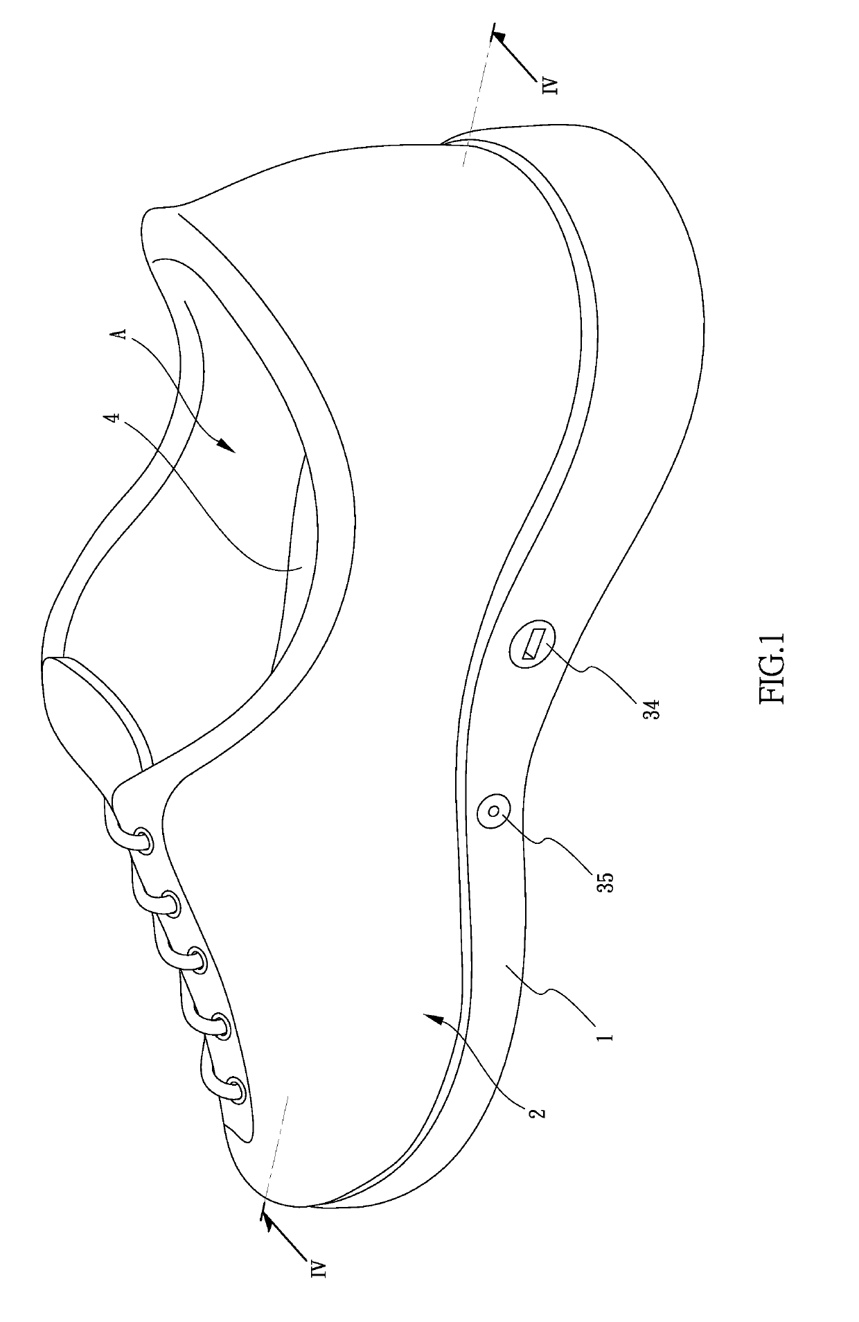
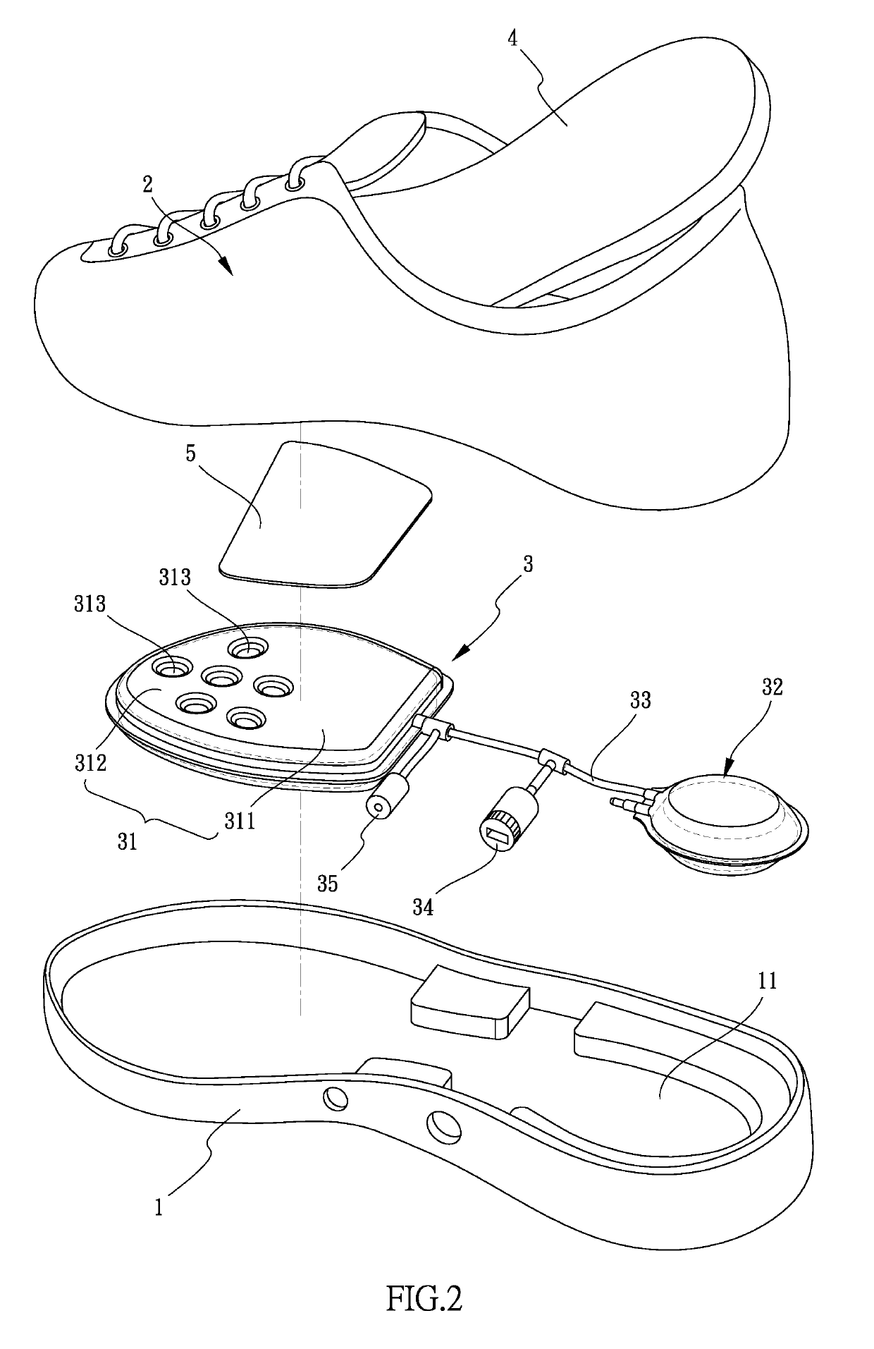
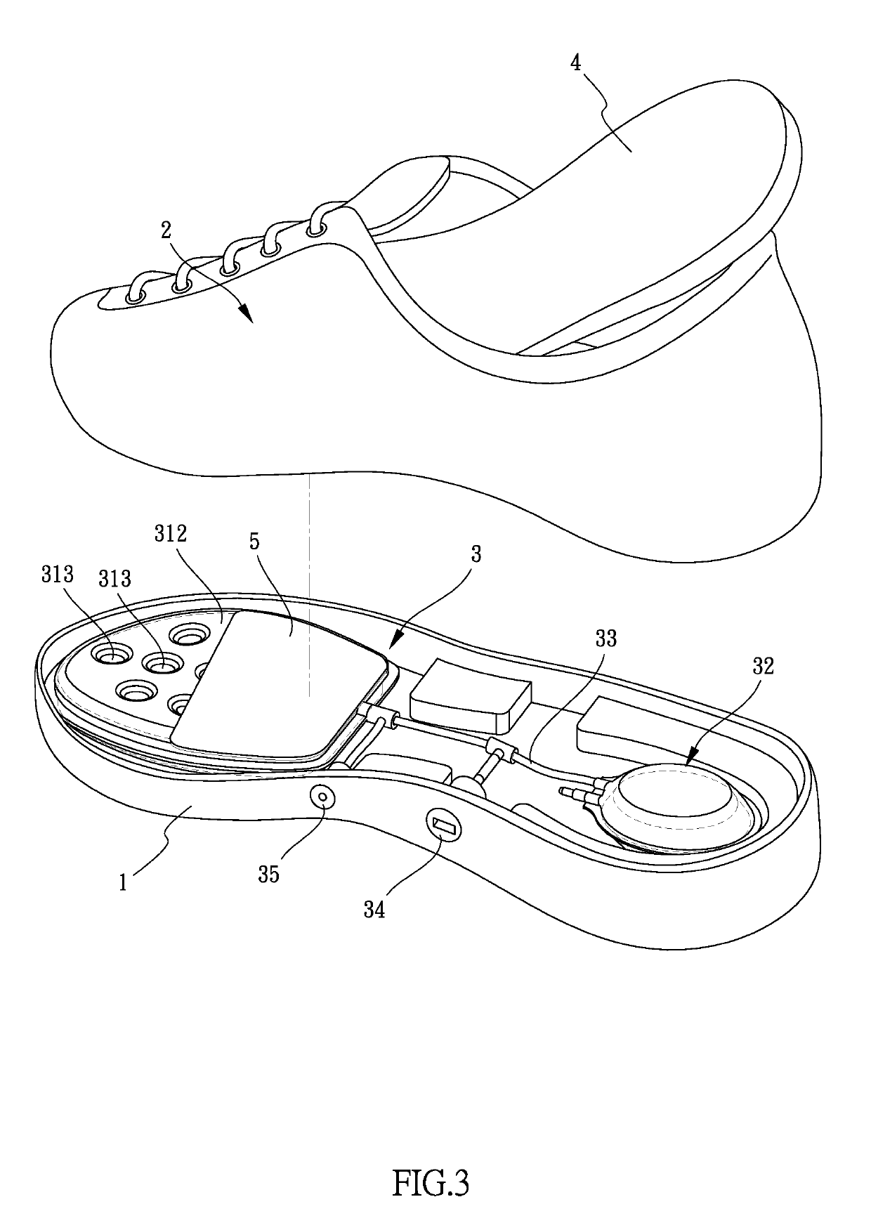
[0023]Referring to FIGS. 1 to 8, the shoe of the present invention comprises an outsole 1 having a room 11 defined in the top thereof and a vamp 2 is connected to the peripheral wall of the room 11. An air pad 3 and an insole 4 are received in the room 11. The insole 4 is and put on the air pad 3. The air pad 3 includes a front pad 31 and a rear pad 32, and a tube 3333 is connected in communication between the front pad 31 and the rear pad 32. A space “A” is defined between the vamp 2 and the insole 4 so that the foot 6 of the wearer is accommodated in the space “A”.

[0024]The tube 33 is connected with an inflation valve 34 and a release valve 35. The inflation valve 34 is able to be accessed from one side of the outsole 1 and introduces air to inflate the front and rear pads 31, 32. The release valve 35 communicates with outside of the outsole 1 and includes a pre-set pressure value and releases pressure from the front pad 31 when a pressure in the front pad 31 reaches the pre-set p...


PUM


Abstract

A shoe includes an outsole having a room defined in the top thereof. A vamp is connected to the peripheral wall of the room. An air pad and an insole are located in the room. The air pad includes a front pad and a rear pad. A tube is connected between the front and rear pads. The front pad includes an inflatable support portion and a resilient support section which is located at the front portion of the front pad. The resilient support section has multiple buffering portions. A plate is located on the front pad and between the inflatable support portion and the insole. The plate restricts the deformation area on the inflatable support portion to deform the insole.

Description

BACKGROUND OF THE INVENTION1. Fields of the Invention[0001]The present invention relates to an inflatable air pad for a shoe, and more particularly, to an inflatable air pad that provides features of comfort and protection to the wearers.2. Descriptions of Related Art[0002]The conventional air pad for a shoe is disclosed in FIG. 9 and generally comprises an air cell 71 on the outsole 70 which is connected to the inside of the vamp 72 so as to form a space for accommodating the wearer's foot 80. An insole 73 is located in the space and covers on the air cell 71. The insole 73 and the air cell 71 absorb shocks transferred from the ground so as to protect the wearer's foot 80. The air cell 71 includes a tube 711 connected thereto which is connected to a valve (not shown). The air cell 71 is inflated by introducing air into the air cell 71 via the tube 711 to achieve the purposes mentioned above.[0003]However, when the air cell 71 inflates, there is a deformation formed on the top of th...

Claims


Application Information

Patent Timeline
Patent Type & Authority Applications(United States)
IPC IPC(8): A43B13/20A43B13/12A43B7/14A43B13/18
CPCA43B13/203A43B13/12A43B7/149A43B13/186
Inventor LO, CHIH-FANG
Owner LO CHIH FANG
Why Eureka
Try Eureka