Air pressure type grouter

A kind of grouting machine and air pressure technology, which is applied in shaft lining, tunnel lining, underground chamber, etc., can solve the problems of poor shockproof effect, uneven cement mortar, affecting the normal use of grouting machine, etc., and achieve the effect of improving the service life

Inactive Publication Date: 2019-03-12
ZHEJIANG JIEYU ENVIRONMENTAL PROTECTION EQUIPCO
View PDF4 Cites 4 Cited by
  • Summary
  • Abstract
  • Description
  • Claims
  • Application Information

AI Technical Summary

Problems solved by technology

Various grouting machines have appeared in the market one after another, and are suitable for many occasions, but the existing grouting machines still have the following problems: 1. The shockproof effect of the grouting machines on the market is poor; 2. The grouting machines on the marke

Method used


Image

  • Air pressure type grouter
  • Air pressure type grouter
  • Air pressure type grouter

Examples


Embodiment Construction

[0021] The following are specific embodiments of the present invention and the accompanying drawings to further describe the technical solutions of the present invention, but the present invention is not limited to these embodiments.

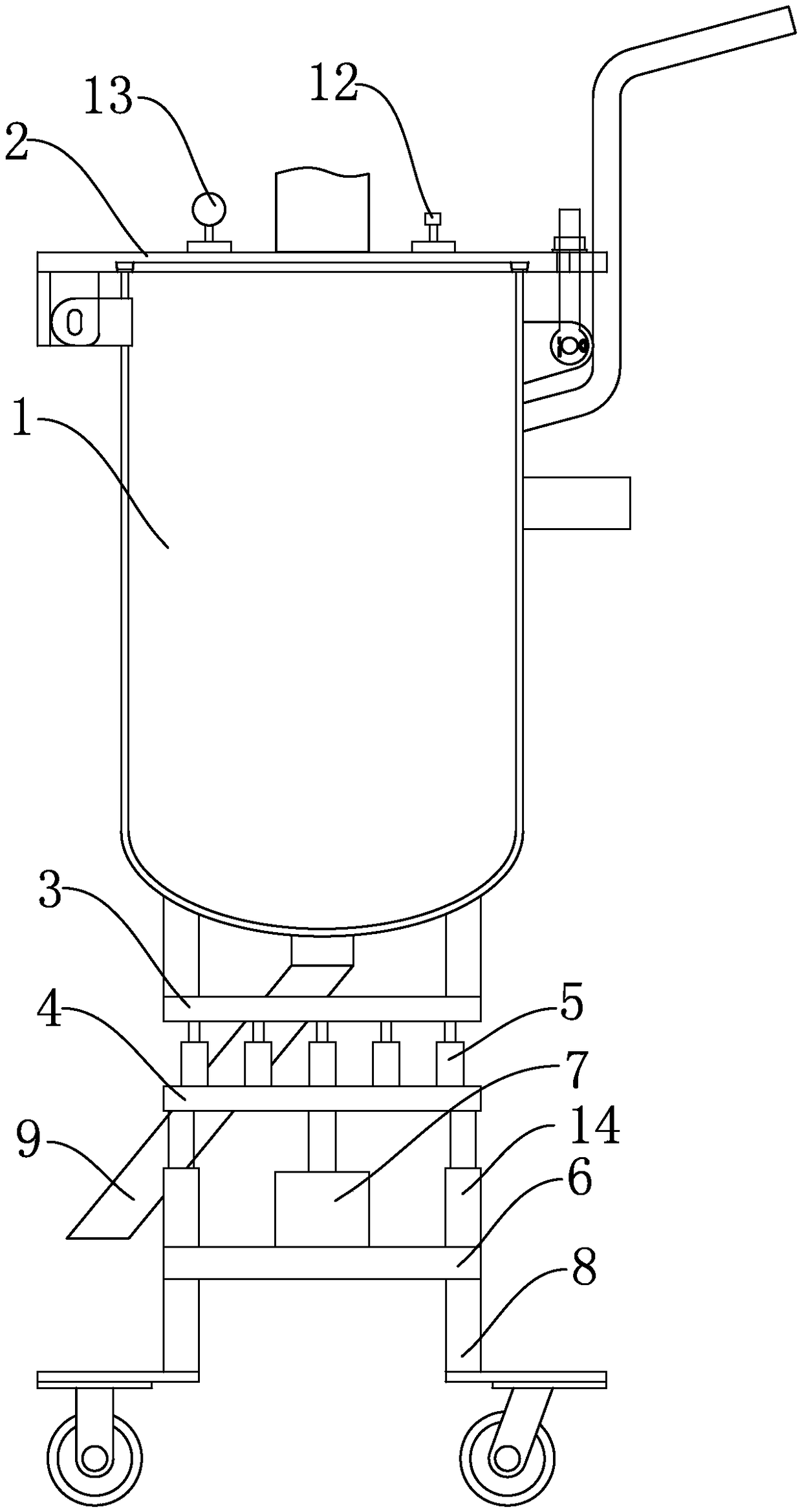
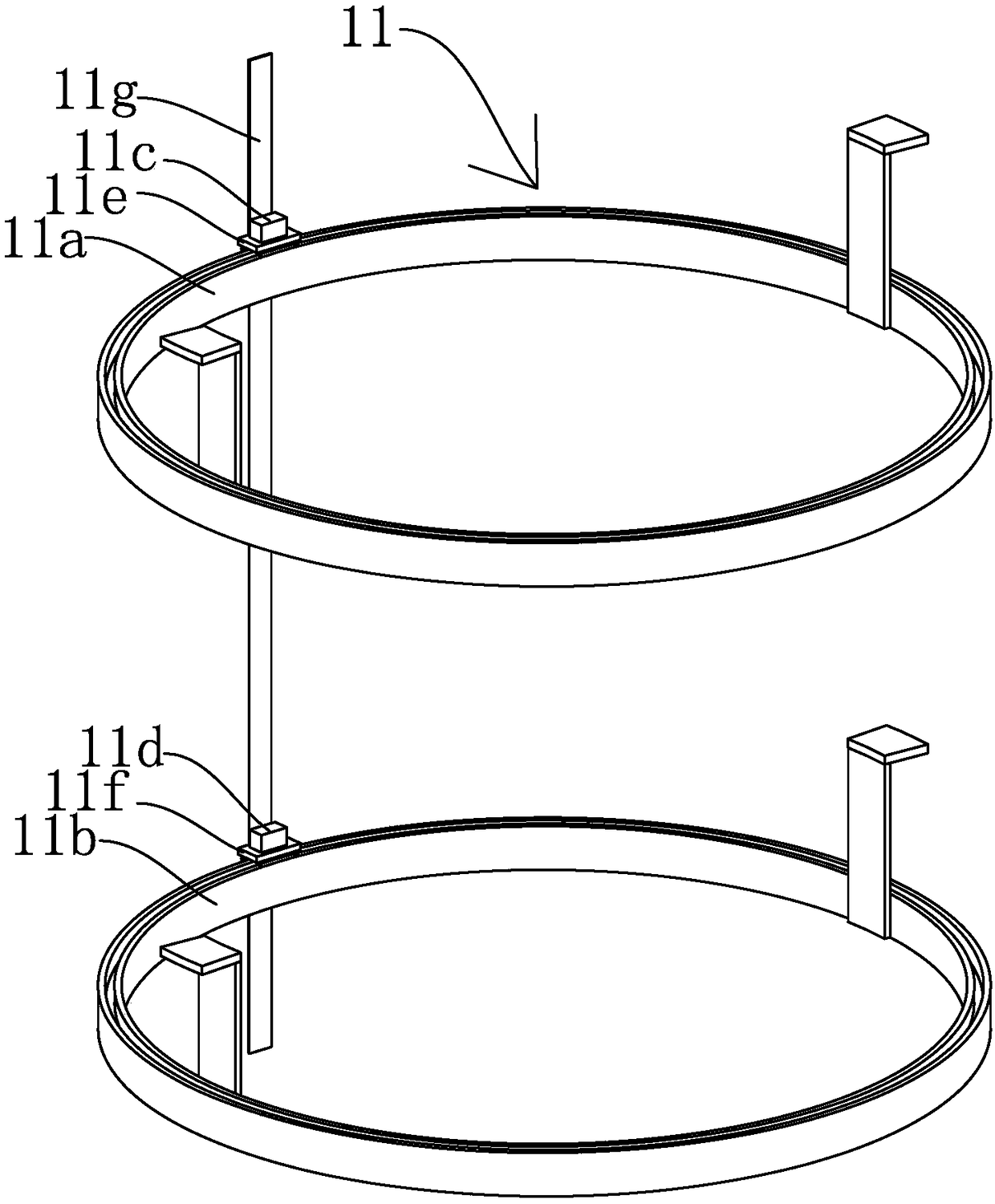
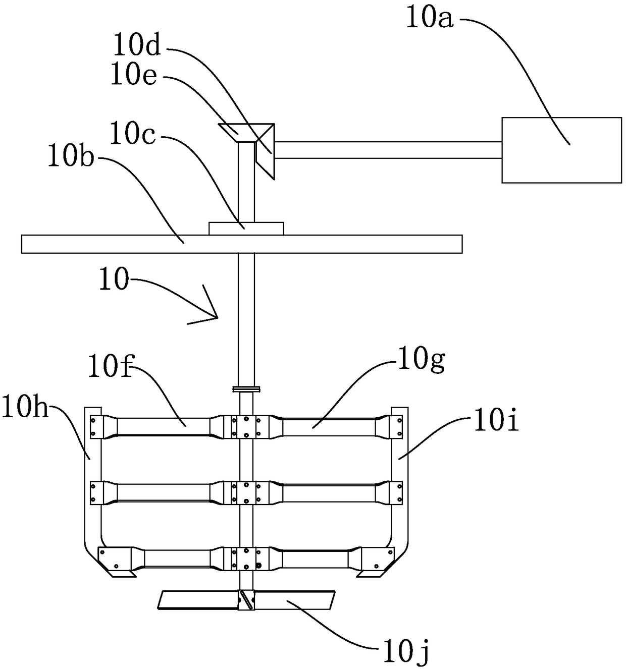
[0022] like Figure 1-3 As shown, a pneumatic grouting machine includes a tank body 1 and an end cover 2. A mounting plate 1 3 and a mounting plate two 4 are fixed under the tank body 1. The mounting plate 1 3 and the mounting plate 2 4 are arranged in parallel up and down, and the mounting plate A number of buffers 5 are arranged between the first 3 and the second mounting plate 4. The buffer 5 has the function of shock absorption. A mounting plate 3 6 is also arranged under the second mounting plate 4, and a hydraulic cylinder 7 is fixed on the third mounting plate 6. The cylinder 7 has the function of lifting and lowering. The piston rod of the hydraulic cylinder 7 is arranged vertically upward and the end is fixed with the mounting plate 2 4...


PUM


Abstract

The invention provides an air pressure type grouter, and belongs to the technical field of grouters. The problem is solved that in the prior art, the property of shock absorbing is poor. The air pressure type grouter comprises a tank and an end cover, a first installing plate and a second installing plate are fixed below the tank and are parallel, multiple buffering devices are arranged between the first installing plate and the second installing plate, a third installing plate is further arranged below the second installing plate, a hydraulic cylinder is fixed to the third installing plate, apiston rod of the hydraulic cylinder is vertically upward, the end of the piston rod and the second installing plate are fixed, multiple supporting legs are fixed to the lower portion of the third installing plate, the end cover is hinged to the tank, an air inlet hole is formed in the top of the end cover and connected with an air compressor, a discharging hole is formed in the bottom of the tank and connected with a discharging pipe, a stirring mechanism for stirring cement mortar is arranged inside the tank, and a clearing mechanism capable of clearing away residues is further arranged inside the tank. The air pressure type grouter has the advantage of shock absorbing.

Description

technical field [0001] The invention belongs to the technical field of grouting machines, and relates to a pneumatic grouting machine. Background technique [0002] The following situations are unavoidable in the construction field: plugging and sealing of cracks, expansion joints, construction joints, and structural joints in various buildings and underground concrete projects; Water leakage from roads, culverts, sewage treatment pools, and concrete cracks, with water plugging; basements, underground garages, underground passages, concrete cracks leaking water, with water plugging; roofing concrete slab cracks, through-wall pipes, corners, seepage Water leakage, plugging with water; cracks in concrete structures, beams, columns, and slabs, reinforcement and reinforcement. All of these situations require grouting, so a grouting machine is required for processing. Various grouting machines have appeared in the market one after another, and they are suitable for many occasio...

Claims


Application Information

Patent Timeline
IPC IPC(8): E04G23/02E02D15/00E21B33/13E21D11/10
CPCE02D15/00E04G23/0203E21B33/13E21D11/10
Inventor 许金生徐佳丽
Owner ZHEJIANG JIEYU ENVIRONMENTAL PROTECTION EQUIPCO
Why Eureka
Try Eureka