
Pier collision prevented device with multiple buffering protection structures

A technology for protecting structures and anti-collision devices, used in road safety devices, bridges, bridge parts, etc., can solve problems such as reduced anti-collision performance, damage to accident vehicles or ships, and rigid protective fences that do not provide protection. Corrosion erosion, cost reduction effect

Inactive Publication Date: 2014-08-27
JIANGSU BOHONG NEW MATERIAL TECH
View PDF6 Cites 4 Cited by
  • Summary
  • Abstract
  • Description
  • Claims
  • Application Information

AI Technical Summary

Problems solved by technology

The rigid anti-collision fence is a non-deformable guardrail device installed on the anti-collision surface of the bridge pier. The main form is a concrete guardrail. The rigid guardrail plays a role in protecting the bridge pier to a certain extent. It does not have an effective protective effect, and causes great damage to accident vehicles or ships; flexible anti-collision facilities have greater cushioning and energy-absorbing performance, and the main form is rubber anti-collision devices, but the cost of rubber anti-collision devices is relatively high. It cannot be widely used in various projects, and the rubber will gradually age in the natural environment, reducing the anti-collision performance

Method used


Image

  • Pier collision prevented device with multiple buffering protection structures
  • Pier collision prevented device with multiple buffering protection structures
  • Pier collision prevented device with multiple buffering protection structures

Examples


Embodiment Construction

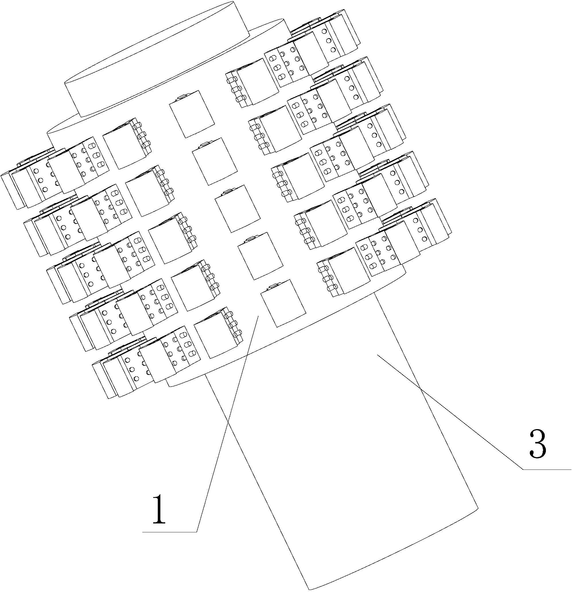
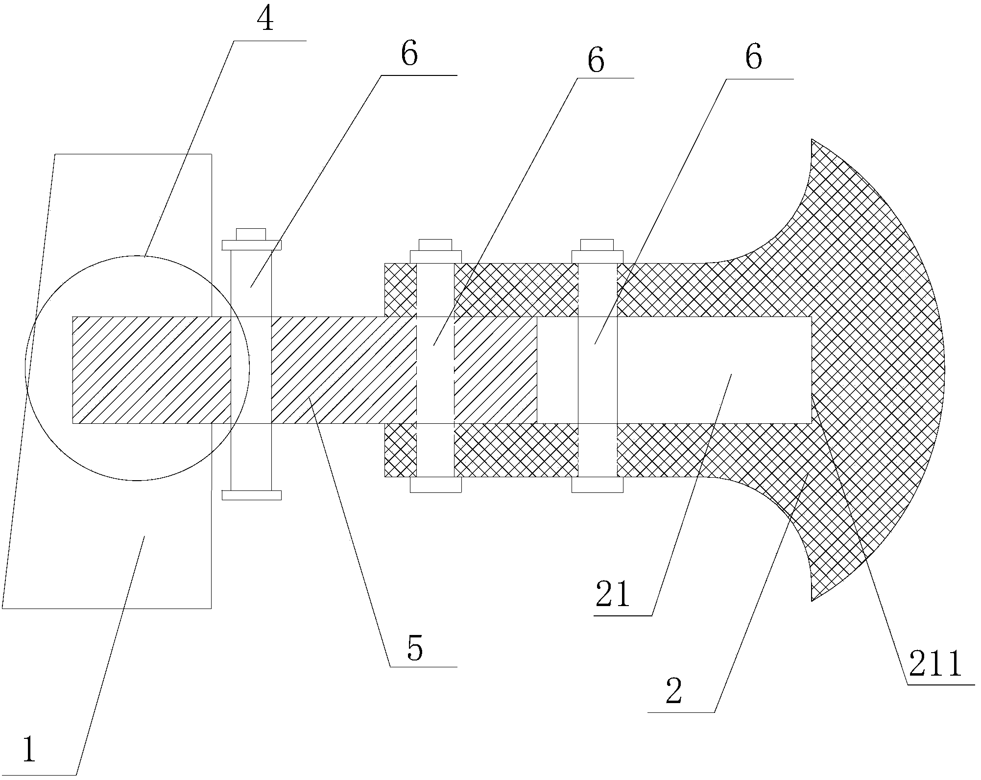
[0021] The invention provides a bridge pier anti-collision device with multiple buffer protection structures, including a composite material fixed layer 1, an anti-collision guardrail 2, and a support column 5, as attached figure 1 As shown: the composite material fixed layer 1 is fixed and covered on the outer surface 3 of the bridge pier above the water surface, and the outer surface of the composite material fixed layer 1 is provided with a concave hole 4, and the anti-collision guardrail 2 is inserted into the composite material through the support column 5. In the concave hole 4 of layer 1,

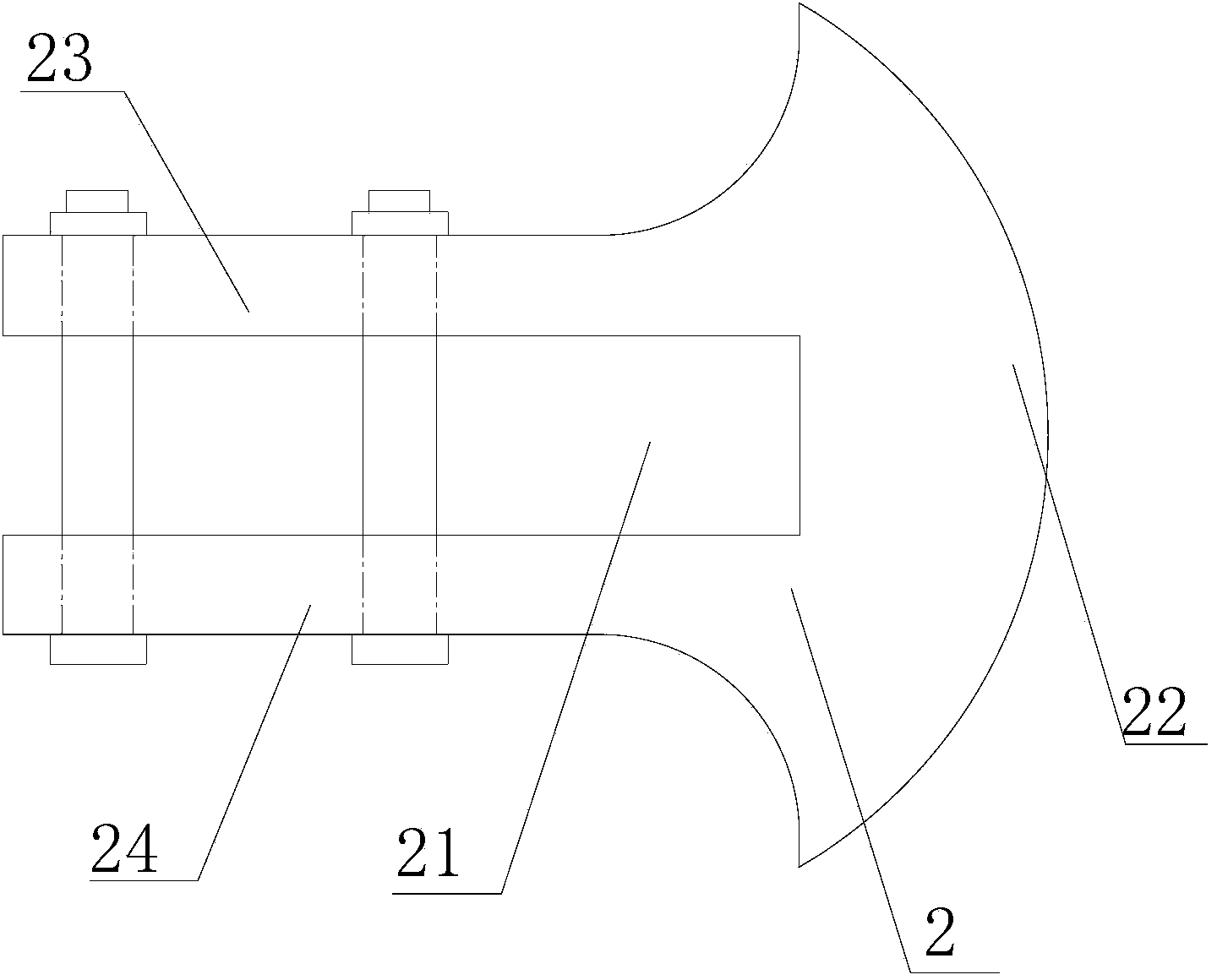
[0022] The structure of crash barrier 2 is as attached image 3 Shown:

[0023] The anti-collision barrier 2 structurally includes an arc-shaped impact contact part 22 (this part directly contacts the hull when the ship collides with the pier, and the part is designed as an arc, which is conducive to changing the impact force when the impact occurs. direction, play a role in buffer...


PUM


Abstract

The invention belongs to the field of bridge roads and particularly relates to a bridge pier collision prevented device. The bridge pier collision prevented device comprises a composite material fixed layer, a collision prevented guardrail and a supporting column; the composite material fixed layer fixedly warps the pier outer surface which is arranged above the water surface; one end of the supporting column and a concave hole of the composite material fixed layer are in insertion joint, the other end and an insertion groove of the collision prevented guardrail are in insertion joint, and two clamping pieces and the supporting column are fixed through bolts, so that the pier collision prevented device plays a role in fixing the collision prevented guardrail and the supporting column; the two clamping pieces which are penetrated by one bolt are fixedly arranged at positions which are arranged between the bottom of the insertion groove and the end portion of the supporting column; the supporting column which is penetrated by one bolt is fixedly fixed at a position from the composite material fixed layer and the collision prevented guardrail. According to the bridge pier collision prevented device, the collision prevented guardrail is avoided from being impacted by a ship body and the composite material fixed layer which warps the pier outer surface is directly impacted and accordingly further protection for the pier is formed.

Description

technical field [0001] The invention belongs to the field of bridges and roads, in particular to a protection and anti-collision device for bridge piers. Background technique [0002] Ship (vehicle) collision accidents have been constantly happening all over the world, and the frequency of boat collision accidents is far higher than we imagined. The loss of life, property damage, and environmental damage caused by ship-bridge accidents is staggering. Many ship collision accidents range from tens of thousands of yuan in losses to casualties in severe cases. The losses are measured in millions, tens of millions or even billions of dollars, and a large amount of indirect losses are even more difficult to calculate. Therefore, it is particularly necessary to take anti-collision measures for bridges. Its fundamental purpose is to prevent bridges from being damaged due to the impact force of ships (vehicles), and at the same time protect ships (vehicles) as much as possible and r...

Claims


Application Information

Patent Timeline
Patent Type & Authority Applications(China)
IPC IPC(8): E01D19/02E01F15/14E02B3/26
CPCY02A30/30
Inventor 陈伟马伟刚杨杰黄宝宝
Owner JIANGSU BOHONG NEW MATERIAL TECH
Learn More