Long and short spiral anchor

A screw anchor, length and short technology, applied in the installation of anchor rods, sheet pile walls, mining equipment, etc., can solve the problems such as the difficulty of effectively guaranteeing durability and bearing capacity, reducing the drilling accuracy of the anchor rod, and reducing the side tension of the anchor rod. , to achieve the effect of improving sharpness and drilling accuracy, high stability of turning holes, and speeding up the speed of turning holes

Pending Publication Date: 2022-01-25
辽宁沈通电力桩基础研发有限公司
View PDF0 Cites 0 Cited by
  • Summary
  • Abstract
  • Description
  • Claims
  • Application Information

AI Technical Summary

Problems solved by technology

At present, when the existing bolt structure is drilling a hole, due to the centrifugal force generated when the bolt rotates, there will be a gap between the hole drilled by the bolt and the bolt, thereby reducing the side tension of the bolt and reducing the Drilling accuracy of bolt
In addition, the hole gap also provides a corrosive environment for the bolt, resulting in a reduction in the bearing capacity, and it is difficult to effectively guarantee the durability and bearing capacity

Method used


Image

  • Long and short spiral anchor
  • Long and short spiral anchor
  • Long and short spiral anchor

Examples


Embodiment 1

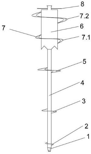
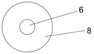
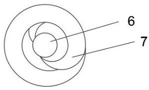
[0035] A long and short helical anchor such as figure 1 , 2 , 3, and 4, including a special-shaped drill bit 1, a first anchor rod 4, a second anchor rod 6, a first solid single-layer spiral blade 2, a second solid single-layer spiral blade 3, and a third annular single-layer spiral blade 5 , the fourth annular multi-layer spiral blade 7 and the top plate 8;

[0036] The bottom end of the first anchor rod 4 is provided with a special-shaped drill bit 1, and the first solid single-layer helical blade 2 is arranged on the top of the first anchor rod 4 at the top of the special-shaped drill bit 1, and the middle part of the first anchor rod 4 is sequentially provided with The second solid single-layer spiral blade 3 and the third annular single-layer spiral blade 5, the top of the first anchor rod 4 is connected to the second anchor rod 6, and the periphery of the second anchor rod 6 is provided with a fourth annular multi-layer spiral blade 7. The top of the second anchor rod ...

Embodiment 2

[0048] A long and short helical anchor such as figure 1 , 2 , 3, including a special-shaped drill bit 1, the first anchor rod 4, the second anchor rod 6, the first solid single-layer helical blade 2, the second solid single-layer helical blade 3, the third annular single-layer helical blade 5, the first solid single-layer helical blade Four annular multi-layer spiral blades 7 and top plate 8;

[0049] The bottom end of the first anchor rod 4 is provided with a special-shaped drill bit 1, and the first solid single-layer helical blade 2 is arranged on the top of the first anchor rod 4 at the top of the special-shaped drill bit 1, and the middle part of the first anchor rod 4 is sequentially provided with The second solid single-layer spiral blade 3 and the third annular single-layer spiral blade 5, the top of the first anchor rod 4 is connected to the second anchor rod 6, and the periphery of the second anchor rod 6 is provided with a fourth annular multi-layer spiral blade 7...


PUM


Abstract

The invention discloses a long and short spiral anchor, and belongs to the technical field of capital construction. The long and short spiral anchor comprises a special-shaped drill bit, a first anchor rod, a second anchor rod, a first solid single-layer spiral blade, a second solid single-layer spiral blade, a third annular single-layer spiral blade, a fourth annular multi-layer spiral blade and a top plate. According to the long and short spiral anchor, the special anchor rod drill bit and three spiral structures of different forms are utilized, drilling holes are stabilized, centrifugal force gaps are reduced, centrifugal force gaps of the drilling holes are reduced by 80% compared with an anchor rod in the prior art, slurry can be smoothly discharged, the situation that the spiral bottoms of the anchor rods are corroded is prevented, and side pulling force, upward pulling force and downward pressing force are enhanced. The long and short spiral anchor is used for foundation construction in electric power, hydraulic power, railways and building industries, the construction method is simple and rapid, and the construction speed is increased by two times or above.

Description

technical field [0001] The invention belongs to the technical field of infrastructure construction, and in particular relates to a long and short spiral anchor. Background technique [0002] Anchor is a commonly used structure in infrastructure engineering. It is a tension member and its system anchored in the ground, which is used to transfer the load of the external structure to the ground to keep the external structure stable. At present, when the existing bolt structure is drilling a hole, due to the centrifugal force generated when the bolt rotates, there will be a gap between the hole drilled by the bolt and the bolt, thereby reducing the side tension of the bolt and reducing the Drilling accuracy of bolts. In addition, the hole gap also provides a corrosive environment for the bolt, resulting in a reduction in the bearing capacity, and it is difficult to effectively guarantee the durability and bearing capacity. The side tension, pull-out force and downforce of conv...

Claims


Application Information

Patent Timeline
Patent Type & Authority Applications(China)
IPC IPC(8): E21D21/00E21D20/00E02D5/74
CPCE21D21/0026E21D20/003E21D21/0006E21D21/0046E02D5/74
Inventor 黄拥杰王建东李东王东兴刘力民张强黄浩李强叶永明季敬源黄海鸣韩冬青贾宏宇王孟男啜镒葛亮
Owner 辽宁沈通电力桩基础研发有限公司
Why Eureka
Try Eureka