

Honeycomb structure
A honeycomb structure and through-hole technology, applied in the direction of colloid chemistry, colloid chemistry, catalyst carrier, etc., can solve the problems of difficult pressure loss, uneconomical, and increase in the total amount of catalyst, and achieve the purpose of suppressing the rise of pressure loss, economy and combustion and removal, efficient combustion and removal effects
Inactive Publication Date: 2009-02-25
IBIDEN CO LTD
View PDF2 Cites 8 Cited by
- Summary
- Abstract
- Description
- Claims
- Application Information
AI Technical Summary
Problems solved by technology
However, it is impossible to burn the deposited particles to shorten the regeneration time of the honeycomb structure to a shorter time than a certain degree, so that it is very difficult to reduce the pressure loss and at the same time regenerate with higher efficiency
In addition, the catalyst needs to be carried on all the through-hole walls, and the total amount of the catalyst will increase, so it is not economical.
[0011] In addition, according to the method described in Patent Document 2, in the honeycomb structure in which the catalyst is supported on the through-hole walls, the efficiency of combustion and removal of fine particles is not sufficient, and there is room for further improvement for efficient purification of exhaust gas.
Method used
View moreImage
Smart ImageViewing Examples

Examples
Embodiment 1~3
[0194] The amount of the catalyst supported on the through-hole walls was set to the value shown in Table 2, a honeycomb fired body was produced, and the following tests were performed.
Login to View More PUM
| Property | Measurement | Unit |
|---|---|---|
| diameter | aaaaa | aaaaa |
| diameter | aaaaa | aaaaa |
| diameter | aaaaa | aaaaa |
Abstract
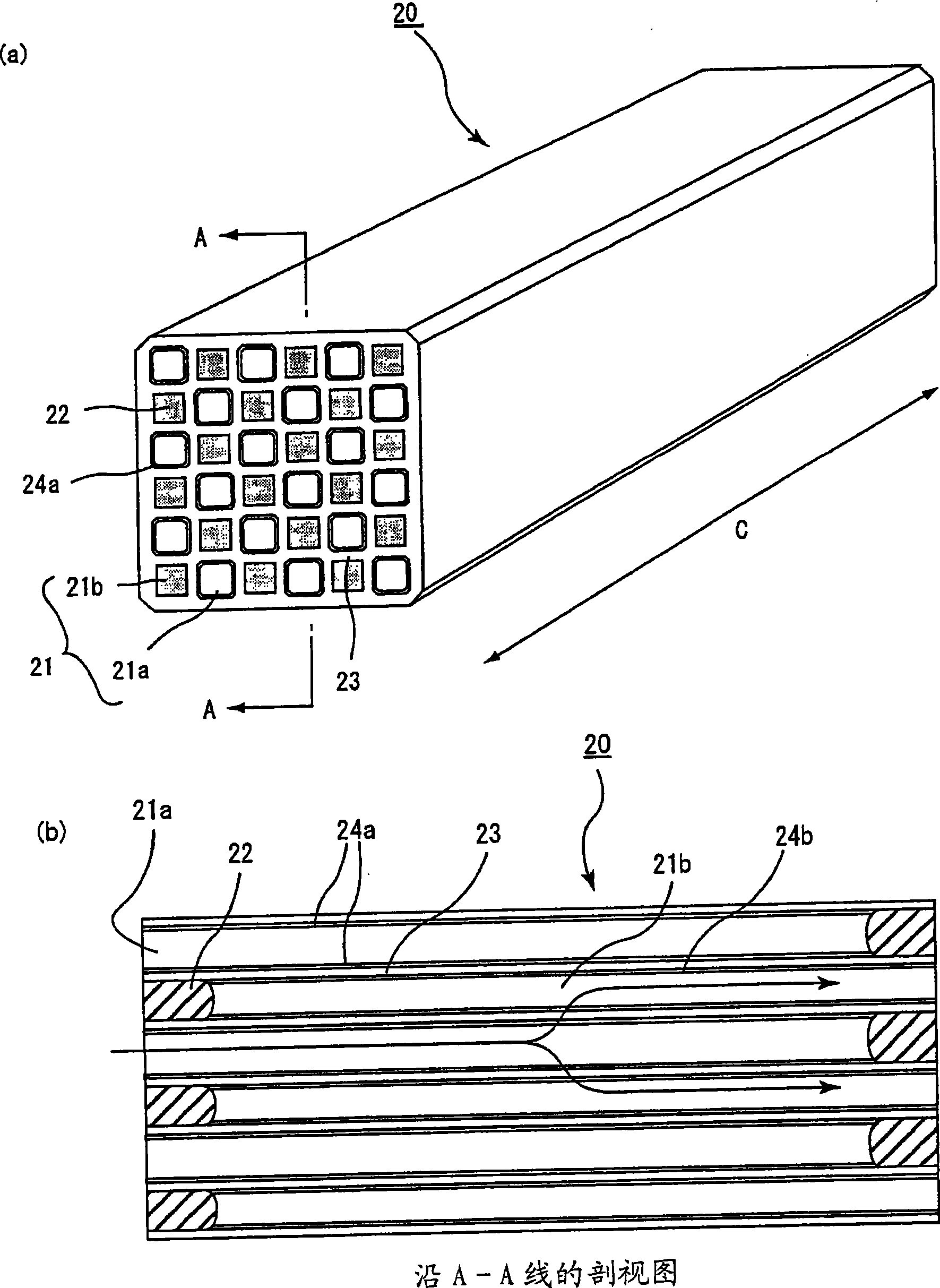
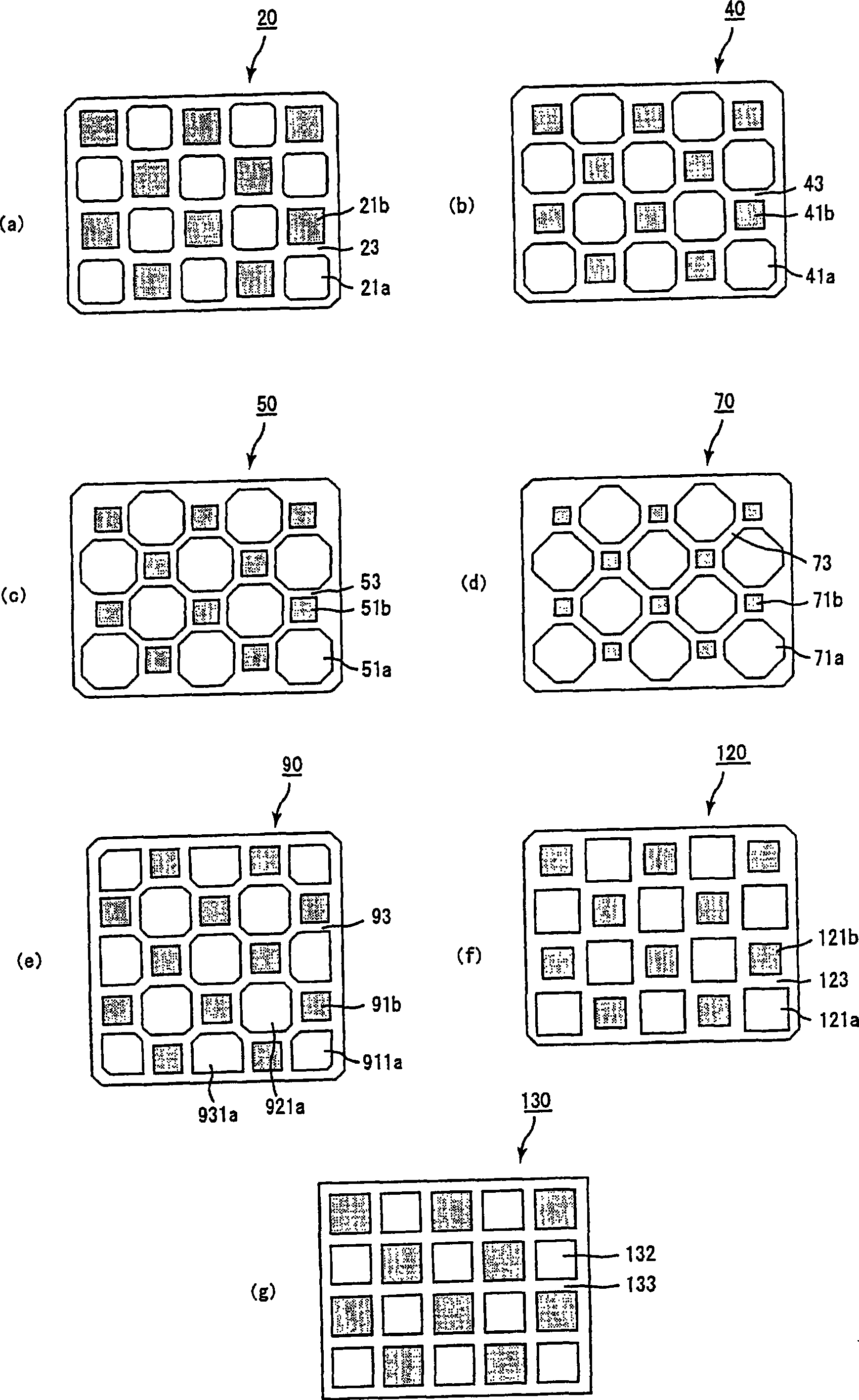
A honeycomb structure that realizes reduction of the amount of catalyst supported and attains not only satisfactory particulate combustion removal but also suppression of pressure loss increase. The honeycomb structure is a columnar one having multiple cells laid parallelly in the longitudinal direction with a cell wall interposed therebetween, either one end portion of each of the cells being sealed by a sealing member, the cell wall supporting a catalyst, characterized in that the multiple cells consist of large-volume cells and small-volume cells, and that the area of section perpendicular to the longitudinal direction of each of the large-volume cells is larger than the area of section perpendicular to the longitudinal direction of each of the small-volume cells, and that while the large-volume cells are sealed at one end portion of the honeycomb structure,; the small-volume cells are sealed at the other end portion of the honeycomb structure, and that the catalyst support is effected only on the cell wall of the large-volume cells, or alternatively the catalyst support is effected on not only the cell wall of the large-volume cells but also the cell wall of the small-volume cells, provided that the amount of catalyst supported on the cell wall of the large-volume cells, per volume, is greater than the amount of catalyst supported on the cell wall of the small-volume cells.
Description
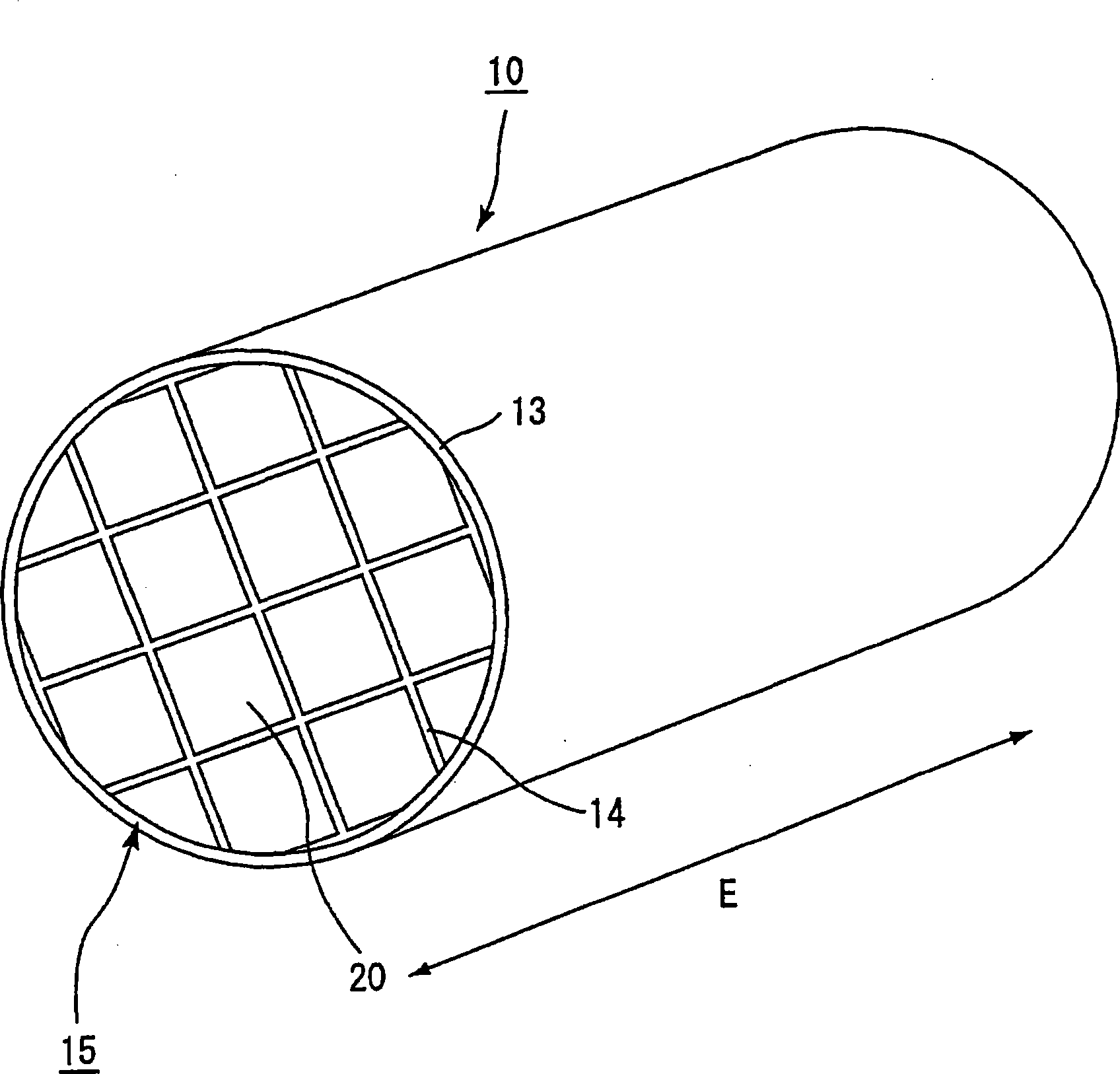
technical field [0001] The present invention relates to a honeycomb structure. Background technique [0002] Particulate matter (hereinafter, also simply referred to as particulate) contained in exhaust gas discharged from vehicles such as buses and trucks and internal combustion engines such as construction machines has recently become a problem because it is harmful to the environment or human body. [0003] Therefore, various honeycomb structures made of porous ceramics have been proposed as filters capable of trapping fine particles in exhaust gas and purifying exhaust gas. [0004] As such a honeycomb structure, known as Figure 6 As shown, a plurality of through-holes 31 are separated in the longitudinal direction ( Figure 6 (direction of arrow D in a)) columnar honeycomb structures 30 arranged in parallel. Such as Figure 6 As shown in (b), either the end portion of the exhaust gas inflow side or the discharge side of the through hole 31 is sealed by the sealing mat...
Claims
Login to View More Application Information
Patent Timeline
 Patent Type & AuthorityApplications(China)
IPC IPC(8): B01D53/94B01D39/14B01D39/20B01D46/00B01J35/04F01N3/02
CPCB01J23/83F01N2330/30F01N3/035F01N2330/34C04B38/0012B01D53/9454C04B38/0016C04B2111/0081Y02T10/22F01N3/0222F01N2450/28B01J35/04F01N3/2828Y10S55/30B01J23/34Y10T428/24157Y02T10/12B01J35/57C04B35/00B01D53/94B01D39/14B01D39/20F01N3/02B01J35/56
Inventor大野一茂国枝雅文
OwnerIBIDEN CO LTD