Electrical connection structure

Active Publication Date: 2019-07-18
FAR EASTERN NEW CENTURY COPRRATION
View PDF0 Cites 2 Cited by
  • Summary
  • Abstract
  • Description
  • Claims
  • Application Information

AI Technical Summary

Benefits of technology

The present invention provides an electrical connection structure for wearable smart devices that improves washability and is easy to mass-produce. The structure is light-weight, thin, and soft, making it comfortable to wear and can be applied to clothing. In addition, it solves the problem of individual wiring of each sensor which results in more labor hours and more cost in prior art. The structure is also applicable to smart devices of composite information sensing. Overall, this invention provides a solution to the problems of prior art and improves the comfort and efficiency of wearable smart devices.

Problems solved by technology

However, bounded by its applications to be worn, the detection of this type of wearable device is directed to a specific part of the body only, and fails to obtain overall physiological sensing information.
In the sensing mode, if these devices are unable to be inclose contact with the skin, the detected results which are captured by the smart device are also resultantly affected.
If the integrated circuits, the electrical connection structure and the sensing elements are simply embedded in the clothing, the rigidity of this kind of electronic module will cause obvious foreign body sensation while wearing and make the clothing unwashable.
However, the electronic module needs to be repeatedly disassembled before laundry, and it is inconvenient to use.
Owing to the rigidity of button and zipper and the significant total weight, smart clothing is less comfortable to wear.
However, its surface is prone to wear or even break so the surface resistance value increases after being subjected to laundry many times so that the conductive fibers are unable to maintain a stable electric conductivity and fail to function normally.
However, as the current technology level is concerned, it is subject to time lag when the information is integrated while the sensing element is transmitting the physiological information back to the signal processing module through the wireless connection.
When continuous and various pieces of information transmitted by the sensing element are needed processing, it is prone to data processing errors.
Therefore, in the technical field it is an important issue to research and to propose a wired electrical connection structure which is suitable for use in a wearable smart device and laundering-resistant to improve the above-mentioned drawbacks in prior art.

Method used


Image

  • Electrical connection structure
  • Electrical connection structure
  • Electrical connection structure

Examples


example 1

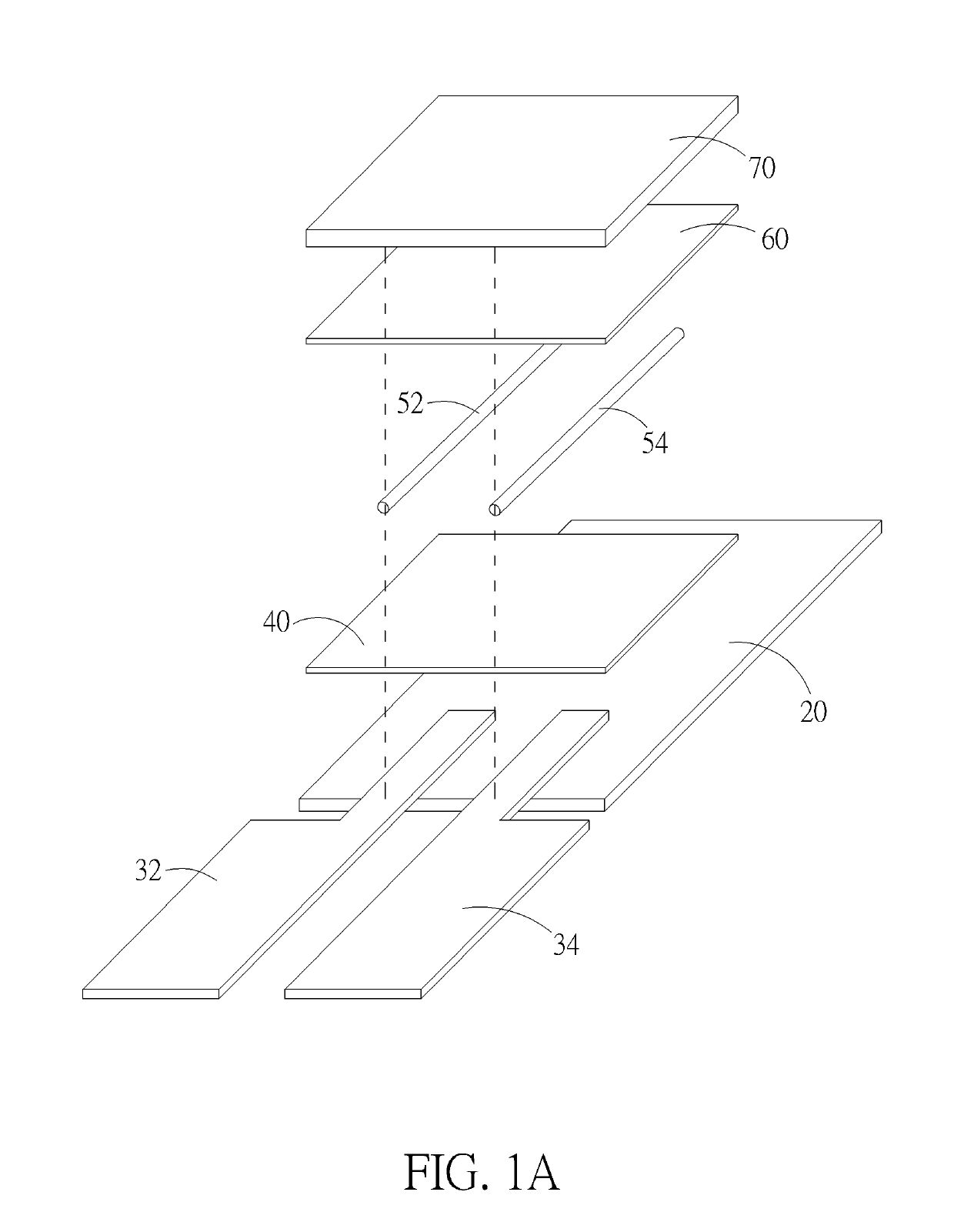
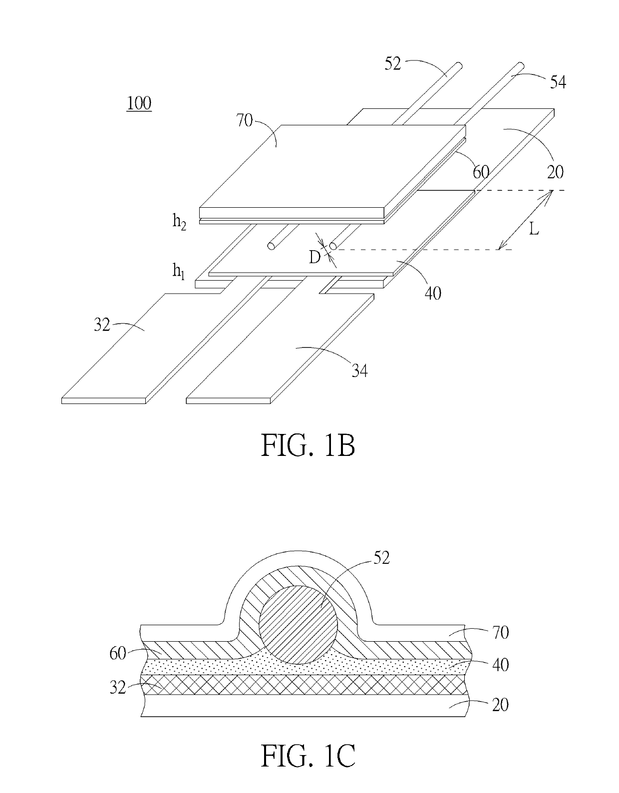
[0103]The preparation of the electrical connection structure includes the following steps:[0104]1. A hot melt adhesive film of 2.5 cm×15 cm was used as a substrate. A prepared first conductive textile layer (0.5 cm×5 cm) and another prepared second conductive textile layer (0.5 cm×5 cm) were arranged at parallel intervals of 0.5 cm between them on the hot melt adhesive film (the side away from the release paper). The preheating is carried out at a temperature of 100° C. for about 5 seconds to fix the hot melt adhesive film and the conductive textile layers. Each contact area of the conductive textile layer and the hot melt adhesive film is 0.5 cm×1.5 cm, and each conductive textile layer has an area of 0.5 cm×3.5 cm which is not in contact with the hot melt adhesive film.[0105]2. An anisotropic conductive adhesive film A of 2.5 cm×1.5 cm was taken to be adhered to the first conductive textile layer and to the second conductive textile layer at the same time. Then, pre-pressing was c...

example 2

[0113]The preparation of Example 2 was the same as that of Example 1 except that Step 4 and Step 5 were altered as follows:[0114]4. A flat needle used for dispensing was filled with 5 g of epoxy resin, and a dispenser was used to coat two copper wires with a coating thickness of 35 μm. Afterwards, the epoxy resin was heated to a temperature of 120° C. for 2 minutes to be cured.[0115]5. The epoxy resin of step 4 was covered with a protective layer of 2.5 cm×1.5 cm and heated by a hot presser at a temperature of 120° C. and under a pressure of 3 kg / cm2 for 60 seconds to obtain another electrical connection structure.

example 3

[0134]The preparation of Example 3 is the same as that of Example 1, except that the anisotropic conductive adhesive film A in Step 2 and in Step 4 was replaced with the anisotropic conductive adhesive film B, and the thickness of the conductive adhesive was 30 μm (excluding the release paper). Therefore, the total thickness of the electrical connection layer and the adhesive layer was 60 μm. The results of the laundering test are listed in Table 3.


PUM

PropertyMeasurementUnit
Thicknessaaaaaaaaaa
Thicknessaaaaaaaaaa
Thicknessaaaaaaaaaa

Abstract

An electrical connection structure is provided in the present invention, which includes a substrate, a plurality of conductive textile layers disposed apart on the substrate, an electrical connection layer disposed on the conductive textile layers, a plurality conductive parts disposed on the electrical connection layer corresponding to the conductive textile layers respectively, an adhesive layer, and a protective layer, wherein the electrical connection layer provides the electrical connection between the conductive textile layers and the conductive parts corresponding to the conductive textile layers, and the conductive textile layers disposed apart from each other are not electrically connected.

Description

BACKGROUND OF THE INVENTION1. Field of the Invention[0001]The present invention relates generally to an electrical connection structure, and more particularly to an electrical connection structure which is suitable for use in a wearable smart device and is laundering-resistant.2. Description of the Prior Art[0002]In recent years, owing to the changes of people's exercise habits and the greatly increased needs for self-management (self-care), quite a few manufacturers have researched and developed a wearable smart device for instantly monitoring the real-time physiological information.[0003]In the beginning, inmost wearable smart devices the integrated circuits and the sensing elements are assembled and connected together through an electrical connection structure to form a single electronic module, and main applications are for use in a smart watch, a smart wristband, or a smart band. However, bounded by its applications to be worn, the detection of this type of wearable device is d...

Claims


Application Information

Patent Timeline
IPC IPC(8): H05K1/03A41D1/00H01B1/22B32B7/10B32B27/08B32B7/12H05K1/02H05K3/32
CPCH05K1/038A41D1/002H01B1/22B32B7/10B32B27/08B32B7/12H05K1/0283H05K3/321H01R4/04H01R11/01H01R11/09A61N1/36014A61B5/6802H05K3/323B32B3/08B32B2307/202B32B2571/00B32B27/40B32B2437/00B32B27/12B32B27/32B32B27/36B32B2250/02B32B2457/00
Inventor WU, YU-CHUNHUNG, WEI-CHELAI, HSIN-KAI
Owner FAR EASTERN NEW CENTURY COPRRATION
Why Eureka
Try Eureka