
Vehicle light assembly having strobe light

a technology of brake light and assembly, which is applied in the field of vehicle brake light assembly, can solve the problems that the driver may not always be alert or aware of the illuminated brake ligh

Active Publication Date: 2019-08-15
FORD GLOBAL TECH LLC
View PDF31 Cites 15 Cited by
  • Summary
  • Abstract
  • Description
  • Claims
  • Application Information

AI Technical Summary

Benefits of technology

The present invention provides a vehicle light assembly and a taillight assembly with a strobe light. The strobe light can be activated when the brake light, reverse light, or turn signal light is activated. The strobe light can have different frequencies and a duty cycle of about 50%. The technical effect of the invention is to provide a more visually appealing and effective lighting system for vehicles.

Problems solved by technology

The enhanced intensity of the brake light is intended to provide a readily recognizable indication of braking for other vehicle drivers; however, some vehicle drivers may not always be alert or aware of the illuminated brake light in a timely fashion.

Method used


Image

  • Vehicle light assembly having strobe light
  • Vehicle light assembly having strobe light
  • Vehicle light assembly having strobe light

Examples


Embodiment Construction

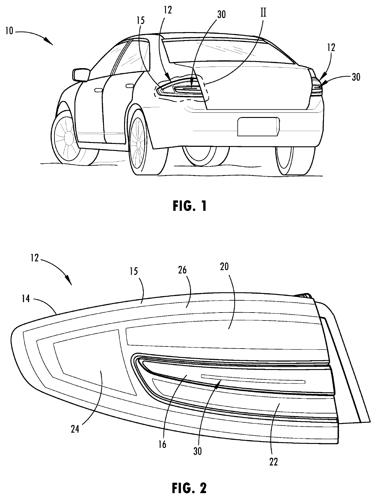
[0036]Referring now to FIG. 1, a motor vehicle 10 is generally illustrated having a pair of light assemblies illustrated as taillight assemblies 12 generally located on the tail or rear end of the vehicle 10 on opposite left and right sides. The vehicle 10 is shown as a passenger car having road wheels for traveling on a road; however, the vehicle 10 may include trucks, vans, SUVs, motorcycles, commercial vehicles and other vehicles that may employ one or more light assemblies and include one or more brake lights. In the embodiment shown, the taillight assembly 12 includes various lighting sources that are selectively illuminated to provide rear lighting, brake lighting, turn signal lighting and reverse lighting that can be selectively activated to be visible by drivers of other vehicles, such as trailing vehicles, as viewed from the rear side of the vehicle 10.

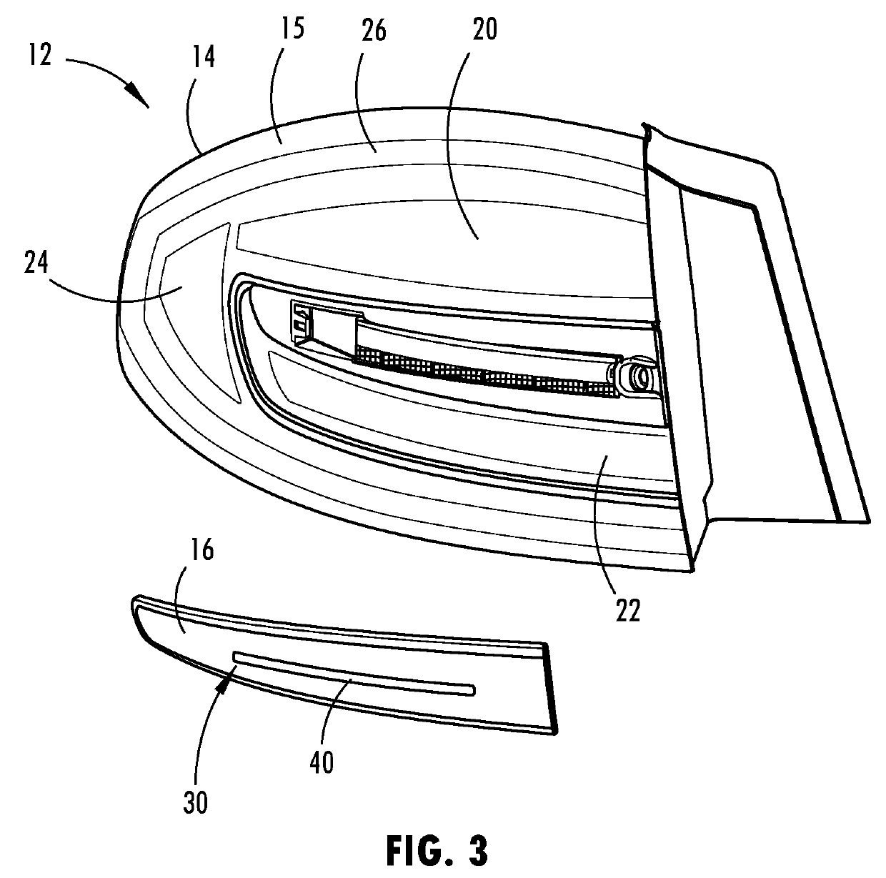
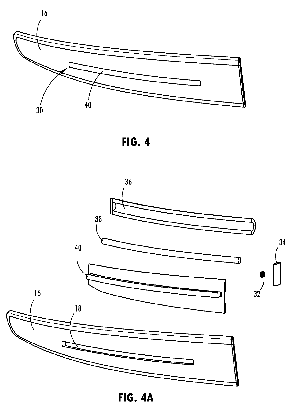
[0037]The taillight assembly 12 is illustrated in FIG. 2 in more detail. The taillight assembly 12 generally includes a hou...


PUM


Abstract

A vehicle taillight assembly is provided that includes a housing having a light transmissive lens, a brake light located in the housing, a strobe light located in the housing and a controller activating the strobe light to strobe when the brake light is activated. The strobe light may also be activated when a turn signal light or reverse light is activated. The strobe light has a light source illuminating light onto a light pipe.

Description

FIELD OF THE INVENTION[0001]The present invention generally relates to vehicle lighting, and more particularly relates to a vehicle brake or taillight assembly having a strobing light.BACKGROUND OF THE INVENTION[0002]Motor vehicles are commonly equipped with taillight assemblies that include brake lights to alert drivers of trailing vehicles when the vehicle brakes are applied during a vehicle braking event. In addition, the taillight assemblies commonly house the vehicle brake lights along with taillights which are typically continuously turned on when the headlights are on, turn signal lights which blink, i.e., turn on and off at a low frequency, to indicate the vehicle may be turning left or right, and reverse lights that illuminate when the vehicle transmission is shifted into reverse gear. The brake lights are typically applied continuously for as long as the brakes are applied and usually illuminate at a higher intensity relative to the taillights. The enhanced intensity of th...

Claims


Application Information

Patent Timeline
IPC IPC(8): B60Q1/46B60Q1/34B60Q1/44H05B33/08F21S43/31F21S43/20H05B44/00
CPCB60Q1/46B60Q1/34B60Q1/44H05B33/0857F21S43/31H05B33/0815F21S43/26B60Q2400/20F21Y2115/10F21Y2113/13B60Q1/2607B60Q1/22F21S43/14F21S43/237F21S43/245F21S43/247F21S43/40F21S43/19F21W2105/00H05B45/20
Inventor SALTER, STUART C.JOHNSON, AARON BRADLEYHELWIG, STEPHEN KENNETHDELLOCK, PAUL KENNETH
Owner FORD GLOBAL TECH LLC
Learn More