Bicycle Derailer Chain Driver

a technology of bicycle derailer and chain driver, which is applied in the direction of chain/belt transmission, vehicle components, cycle equipment, etc., can solve the problems of lack of highly desirable accuracy of position held, lack of novel solution, and inability to achieve effective solution to challenging problem

Active Publication Date: 2019-08-22
HAMED HAZEM NIHAD
View PDF5 Cites 8 Cited by
  • Summary
  • Abstract
  • Description
  • Claims
  • Application Information

AI Technical Summary

Benefits of technology

[0012]Inventor discloses an improved bicycle powertrain design overcoming the shortcomings of the standard derailer inability to shift while the bicycle is in a stationary state through addition of an auxiliary chain driver apparatus granting the rider the ability to execute the otherwise unavailable desired stand still shifting function.

Problems solved by technology

As a shift operation less any chain motion sensors confirming shift action is possible, is likely to prove detrimental to the confined and prone to overheating motor, attempt has been made for the derailer to reach intended positon during shift notwithstanding lack of chain motion so that applied power would cease short of burning the small motor windings.
It is noteworthy to indicate that this problem does not resolve the shortcoming of the legacy derailer of not being able to shift less chain motion, this approach simply attempts to overcome the aforementioned challenge inherent to the legacy shifter design.
Moreover, an unintended result of this provision is the lack of highly desirable accuracy of the position held by the derailer since reaction by a mechanical spring is typically proportionate to displacement so that the derailer final settling position, although typically close, is nevertheless never reached due spring hysteresis and offset by the encountered resistance by the chain and mechanical friction within the derailer linkage.
Notwithstanding the long recognized need for alleviating the bicycle rider from the undue effort necessary for reinitiating bicycle motion after a sudden stop due to the bicycle drivetrain being in the wrong setting, an effective solution to this challenging problem has proven highly elusive.
Lack of disclosed art along with lack of commercially successful and thereby available products providing shifting capability to the standard de-facto derailer design during a complete stop is proof of lack of a novel solution to this challenging problem.

Method used


Image

  • Bicycle Derailer Chain Driver
  • Bicycle Derailer Chain Driver
  • Bicycle Derailer Chain Driver

Examples


Embodiment Construction

[0050]Preferred Embodiment Construction—FIGS. 1-2.

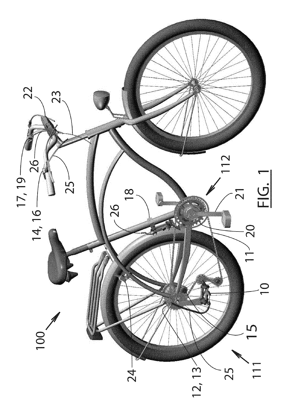
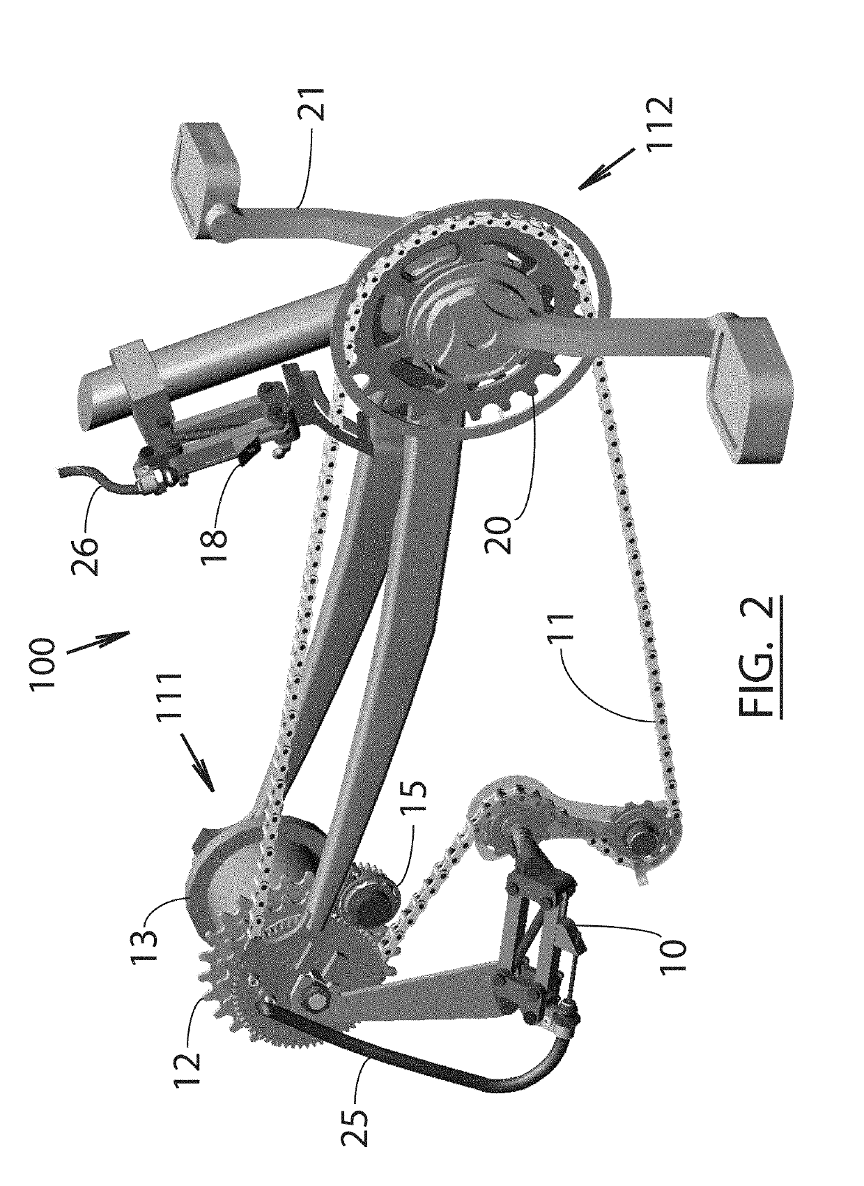
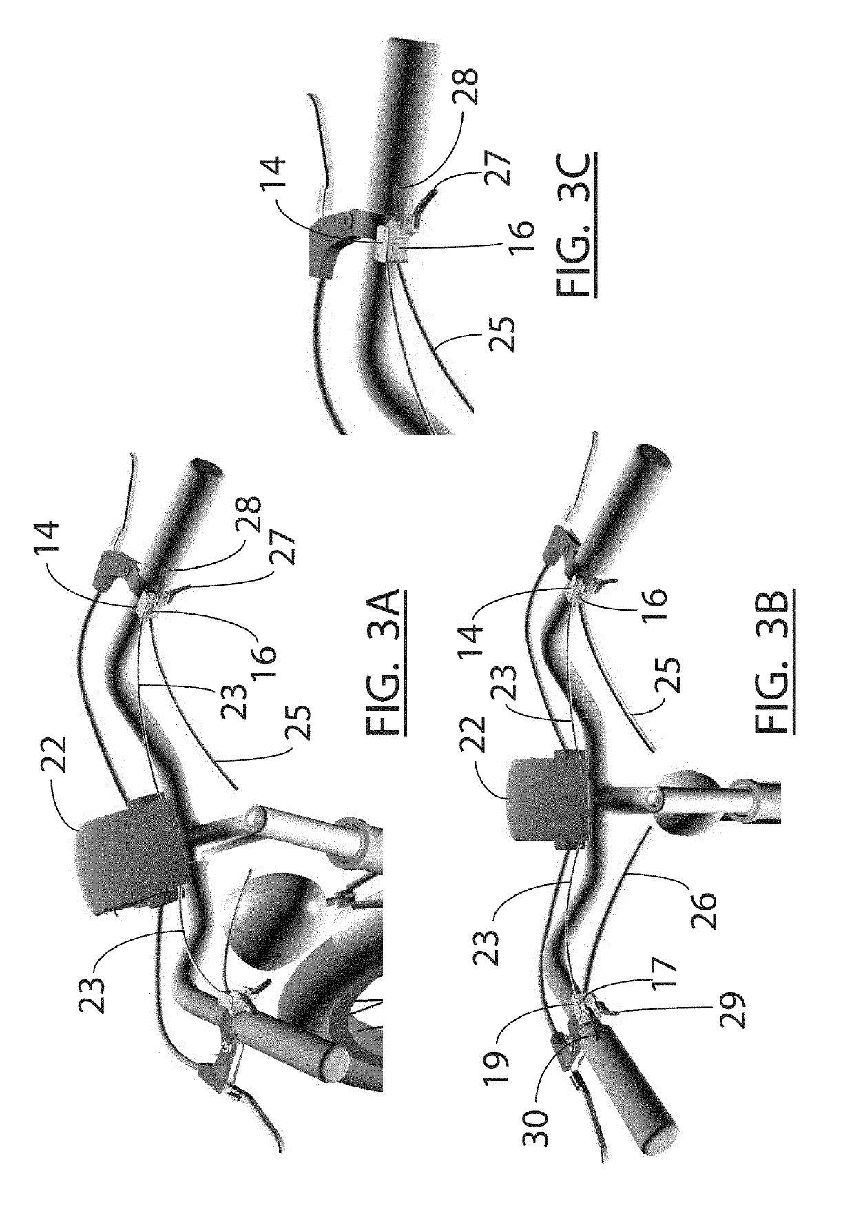
[0051]With reference to FIGS. 1 & 2, arrangement 100 of a manual derailer based bicycle making use of the preferred embodiment chain driver of the present invention comprises manual rear derailer assembly 10 serving to alternate chain 11 between sprockets 12 of rear drive hub assembly 13 through right derailer shifter 14 located on the bicycle right handlebar, chain driver motor 15 of chain driver apparatus 111 serving to energize chain 11 in the forward direction under rider command by right chain driver switch 16 located on the right handlebar and left chain driver switch 17 located on the left handlebar in instances of lack of chain motion thereof when shifting is desired, manual front derailer assembly 18 actuated through front derailer shifter 19 located on the left handlebar serving to alternate chain 11 between front sprockets assembly 20 of pedals ratchet apparatus 112 serving to sever power transmission to pedals assembly 21...


PUM


Abstract

A manually controlled chain driver apparatus for a bicycle drive chain derailer providing necessary forward chain movement less power transmission to bicycle pedals for derailer operation during stopping and coasting instances when pedaling motion has ceased or is not possible.

Description

CROSS-REFERENCE TO RELATED APPLICATIONS[0001]Not ApplicableFEDERALLY SPONSORED RESEARCH[0002]Not ApplicableSEQUENCE LISTING OR PROGRAM[0003]Not ApplicableFIELD OF THE INVENTION[0004]The disclosed invention relates to the cycling transportation and sporting industry, specifically to modern bicycle designs typically making use of front and rear drive chain derailers serving to alternate drive chain position between different ratio front and rear drive sprockets through linkage to a set of rider control levers permitting the rider to achieve an optimal drivetrain ratio through selection of an adequate combination of front and rear drive sprockets, thereby facilitating a comfortable pedaling rate and effort thereof depending on desired road speed, rider conditioning, road inclination and other circumstantial conditions.BACKGROUND OF THE INVENTION[0005]Bicycles have existed for many years throughout serving as transportation and sporting means. Over the great time span since their incept...

Claims


Application Information

Patent Timeline
Patent Type & Authority Applications(United States)
IPC IPC(8): B62M9/122
CPCB62M9/122B62M9/1242B62M25/08B62M6/90B62M9/123B62M9/128B62M9/16
Inventor HAMED, HAZEM NIHAD
Owner HAMED HAZEM NIHAD
Why Eureka
Try Eureka