
Vibration reduction device

a technology of vibration reduction and reduction device, which is applied in the direction of rotational vibration suppression, vibration suppression adjustment, slip coupling, etc., can solve the problems of torsional vibration being transmitted from excessive torsional vibration in the vibration reduction device, so as to reduce the relative displacement between the input member and the inertia mass body, and stably attenuate the torsional vibration

Inactive Publication Date: 2019-08-22
EXEDY CORP
View PDF11 Cites 2 Cited by
  • Summary
  • Abstract
  • Description
  • Claims
  • Application Information

AI Technical Summary

Benefits of technology

The present vibration reduction device is designed to prevent excessive torsional vibration by limiting the transmission of torque between the input rotary part and the damper part. This results in an appropriately operated device that can stably attenuate torsional vibration. In simple terms, this device blocks or suppresses excessive vibration, making it easier to operate and reducing the likelihood of damage or malfunction.

Problems solved by technology

In this case, the period between after the start of the engine and until the rotational speed of the engine is stabilized, the rotational speed of the engine is unstable causing an excessive torque fluctuation to be input to the vibration reduction device from the engine, and therefore there is a risk that an excessive torsional vibration might occur in the vibration reduction device.
Also, after the rotational speed of the engine is stabilized, the operation of the dynamic damper device can cause a resonance, for example, a secondary resonance of the vibration reduction device to occur.
Therefore, an excessive torsional vibration can occur in the vibration reduction device.
That is, when an excessive torsional vibration as described above occurs in the vibration reduction device, the vibration reduction device cannot completely absorb the torsional vibration, and therefore there is a risk that the torsional vibration might be transmitted from the vibration reduction device to a member on the transmission side.

Method used


Image

  • Vibration reduction device
  • Vibration reduction device
  • Vibration reduction device

Examples


Embodiment Construction

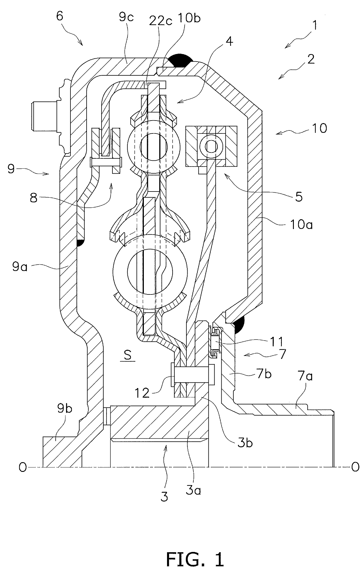
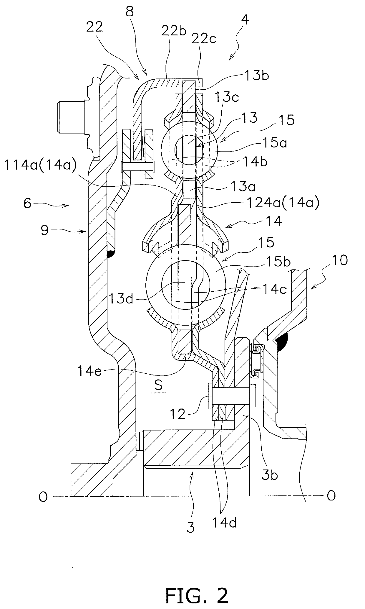
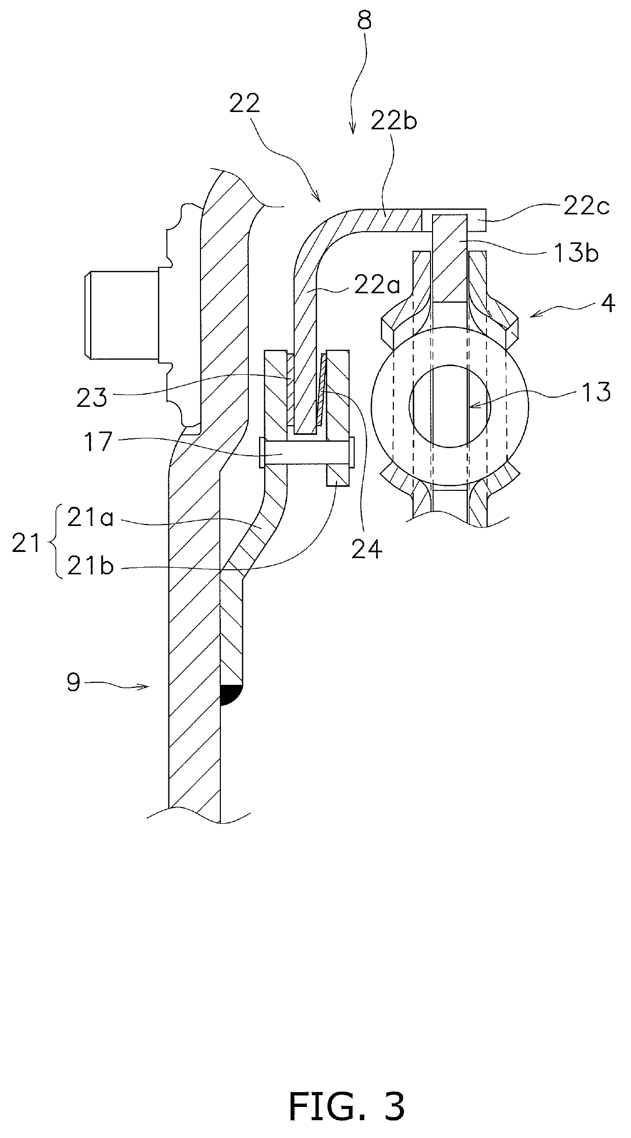
[0049]FIG. 1 is a cross-sectional view of a vibration reduction device according to an exemplary embodiment of the present disclosure. In FIG. 1, an engine (not shown in the drawing) is disposed on the left side whereas a transmission (not shown in the drawing) is disposed on the right side of the drawing. It should be noted that a line O-O depicted in FIG. 1 indicates a rotational axis of a vibration reduction device 1. It should also be noted that hereinafter, a direction away from the rotational axis O may be referred to as “radial direction”; a direction along the rotational axis O may be referred to as “axial direction”; and a direction around the rotational axis O may be referred to as “circumferential direction”.

[0050][Overall Configuration of the Vibration Reduction Device]

[0051]The vibration reduction device 1 is a device for transmitting a torque from a member on the engine side to a member on the transmission side. Further, the vibration reduction device 1 is configured t...


PUM


Abstract

A vibration reduction device for reducing a torsional vibration from an engine includes an input rotary part, an output rotary part, a damper part, a dynamic vibration absorbing device, and a torque limiting part. Torsional vibration is input to the input rotary part. The output rotary part is disposed to be relatively rotatable with respect to the input rotary part. The damper part is disposed between the input rotary part and the output rotary part and attenuates the torsional vibration input to the input rotary part. The dynamic vibration absorbing device absorbs the torsional vibration output from the damper part. The torque limiting part limits transmission of torque between the input rotary part and the output rotary part.

Description

CROSS-REFERENCES TO RELATED APPLICATIONS[0001]This application is the U.S. National Phase of PCT International Application No. PCT / JP2017 / 027270, filed on Jul. 27, 2017. That application claims priority to Japanese Patent Application No. 2016-163972, filed Aug. 24, 2016. The contents of both applications are herein incorporated by reference in their entirety.BACKGROUNDTechnical Field[0002]The present disclosure relates to a vibration reduction device.Background Art[0003]A conventional vibration reduction device is disposed between an engine and a transmission to reduce torsional vibration from the engine. The conventional vibration reduction device includes a housing (flywheel element 3), an output member (flywheel element 4), a damper part (energy accumulator 10) disposed radially outward, and a dynamic vibration absorbing device (vibration attenuator 10) that is disposed farther radially inward than the damper part.BRIEF SUMMARY[0004]In the conventional vibration reduction device,...

Claims


Application Information

Patent Timeline
Patent Type & Authority Applications(United States)
IPC IPC(8): F16F15/134F16F15/14F16D7/02
CPCF16F15/13469F16F15/145F16D7/025F16D7/02F16F15/1428F16F15/1297F16F15/134F16F15/00F16F15/14
Inventor KAWAHARA, YUKITOMITA, YUSUKEOKAMOTO, YUSUKE
Owner EXEDY CORP
Learn More