Electrostatically actuated device

a technology of electro-actuation and actuator, which is applied in the direction of positive-displacement liquid engines, spectacles/goggles, instruments, etc., can solve the problems of low power efficiency and inability to adapt to the need of reversible pumping, and achieve the effect of reducing the capacity formed by the first deformable portion and the first primary surfa

Active Publication Date: 2019-08-22
LACLAREE
View PDF0 Cites 3 Cited by
  • Summary
  • Abstract
  • Description
  • Claims
  • Application Information

AI Technical Summary

Benefits of technology

[0012]Thus, this configuration allows the displacement of a second fluid squeezing the first fluid inside or outside the electrode chamber. Another aspect of the invention is to add a limitation to the expansion of the electrode chamber in order to control the movement of the deformable electrode.
[0084]Thus, this configuration allows having at the same time a large electrode area facing the membrane in order to maximize the electrostatic actuation and an effective fluidic communication through the partition wall.

Problems solved by technology

The main problem raised by these concepts is that they are usually designed for continuous operations like circulating continuously small fluxes of liquids through a pipe.
As a consequence they are slow, and exhibit very low power efficiency, and for some one a power efficiency less than 0.1.
Clearly they are not adapted to the need of the reversible pumping of a limited quantity of liquid and using low power consumption.

Method used


Image

  • Electrostatically actuated device
  • Electrostatically actuated device
  • Electrostatically actuated device

Examples


first embodiment

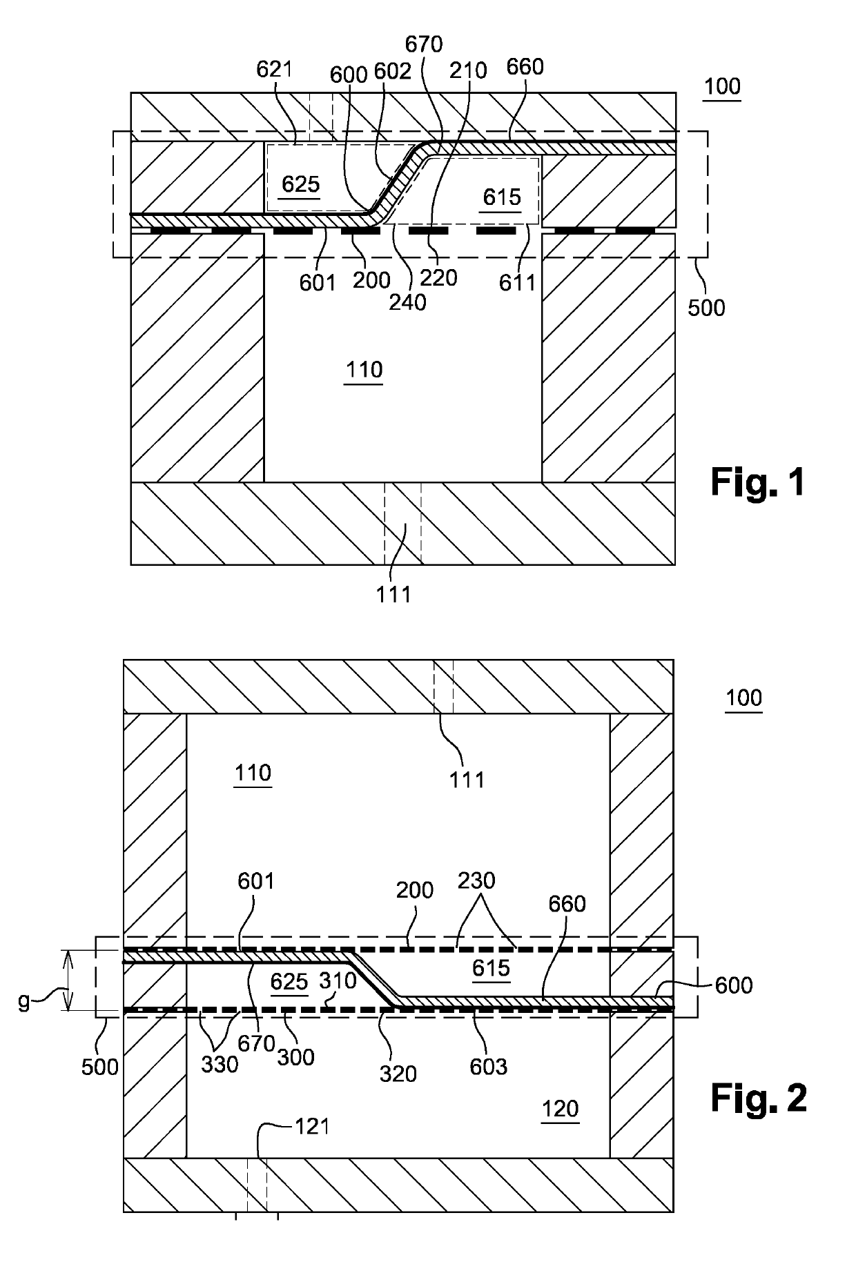
[0099] shown on FIG. 1, an electrostatically actuated device 100 configured to apply only a unidirectional force is disclosed. The electrostatically actuated device 100 comprises a first chamber 110. The first chamber 110 is configured to comprise a first fluid.

[0100]This first fluid may be configured to go through a first primary fluid passage 111, which means that the first fluid may have an engineered viscosity. This first primary fluid passage 111 may emerge outwardly, preferably outward of the first chamber 110. This first primary fluid passage 111 may be located on one side of the first chamber 110.

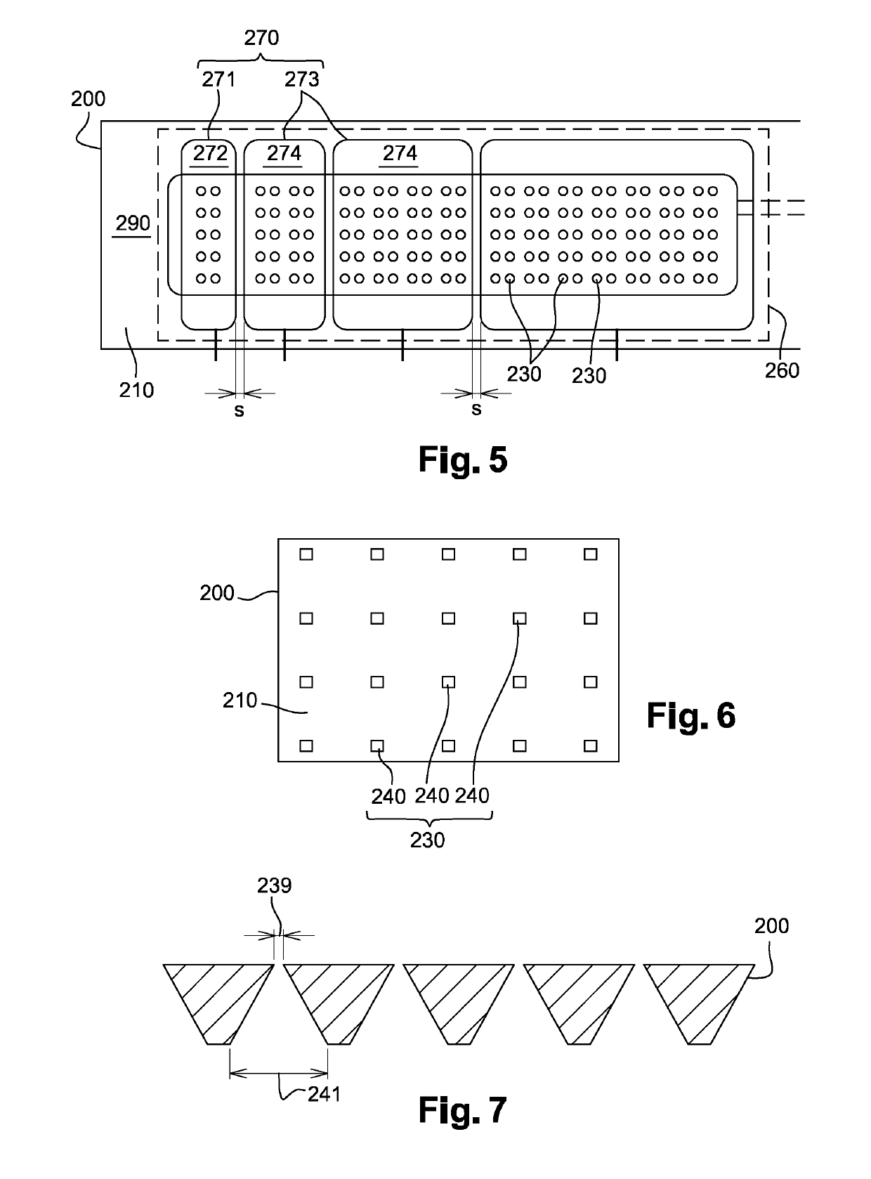
[0101]The first chamber 110 may be at least partially defined by a primary partition wall 200. This primary partition wall 200 may comprise a first primary surface 210, a second primary surface 220 and a plurality of second primary fluid passages 230. The second primary surface 220 may face the first chamber 110 and more precisely the second primary surface 220 may face the first pr...

third embodiment

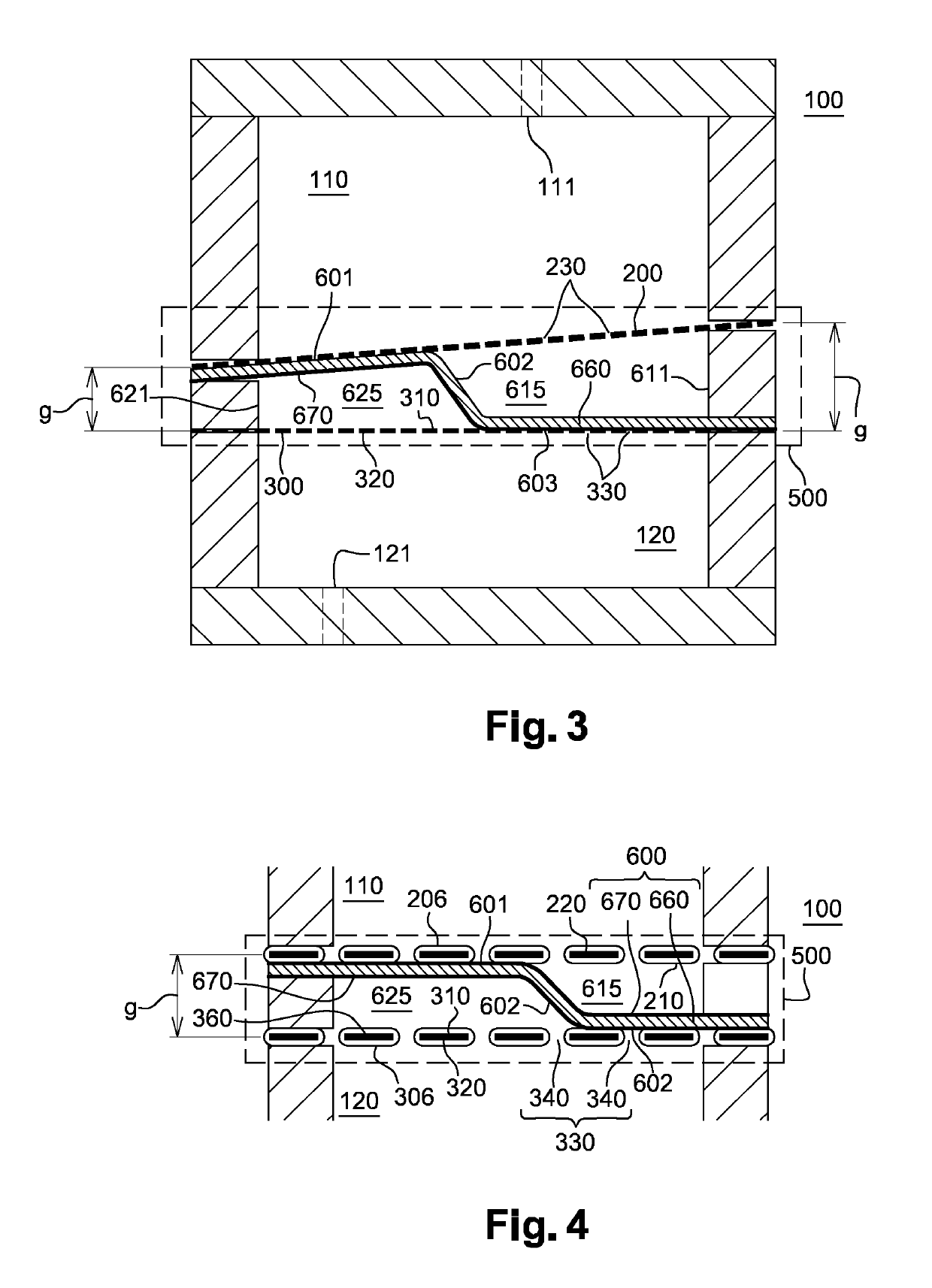
[0116] shown on FIG. 3, the primary partition wall 200 and the secondary partition wall 300 may form a wedge or a slope such that the gap or wall distance g between the primary partition wall 200 and the secondary partition wall 300 may increases from one side of the electrode chamber 500 to the other. The gradient of thickness of the gap g insures a smooth transition of the electrostatically actuated device 100 with voltage as will be discussed later.

[0117]At least one of the partition walls among the primary partition wall 200 and the secondary partition wall 300, which may have a wall distance g smaller than 600 μm between them, and preferably smaller than 200 μm between them, may comprise a primary electroconducting pad. According to the embodiment shown on FIG. 3, the wall distance g between the primary partition wall 200 and the secondary partition wall 300 may vary such as to have a slope.

[0118]More precisely, the wall distance g between the primary partition wall 200 and the...

fourth embodiment

[0120] shown on FIG. 4, the primary partition wall 200 and the secondary partition wall 300 may be a part of the electrode by being connected to the higher voltage and to the lower voltage or vice versa and the PET deformable electrode 600 at the common reference or electrical ground. More precisely, there may be an primary electroconducting pad 270 on the first primary surface 210 and an secondary electroconducting pad on the first secondary surface 310 which is electrically connected to the higher voltage and to the lower voltage or vice versa and the PET deformable electrode 600 may comprise a deformable electroconducting layer 670 at the common reference or electrical ground.

[0121]In a particular embodiment wherein the deformable electroconducting layer 670 may be disposed on both side of the deformable electrode 600, the primary partition wall 200 and the secondary partition wall 300 will be insulated by an insulating layer 206 which can be deposit by at least of the method, bu...


PUM


Abstract

The present invention relates to an electrostatically actuated device comprising at least first chamber, an electrode chamber comprising a deformable electrode. The deformable electrode is disposed in the electrode chamber such as to form a first electrode chamber and a second electrode chamber.

Description

CROSS REFERENCE TO RELATED APPLICATIONS[0001]This application is a National Stage of PCT Application No. PCT / EP2017 / 071712 filed on Aug. 30, 2017, which claims priority to French Patent Application No. 16 / 58119 filed on Sep. 1, 2016, the contents each of which are incorporated herein by reference thereto.TECHNICAL FIELD OF THE INVENTION[0002]This invention relates to the field of displacement machines for liquids, which are used in particular in variable ophthalmic devices in order to improve the quality of vision of a patient by using liquids in the lenses as described in the patent application FR 16 / 56610. More specifically, this invention deals with electrostatics pump and precisely with electrostatics actuated devices using a membrane to displace at least one fluid.BACKGROUND[0003]Some classical devices used to displace an amount of fluid, have been designed with micro-fabrication technologies like MEMS, using piezoelectric actuators for instance. The main problem raised by thes...

Claims


Application Information

Patent Timeline
Patent Type & Authority Applications(United States)
IPC IPC(8): G02C7/08F04B19/00F04B43/04
CPCG02C7/085F04B19/006F04B43/043G02B3/14G02B26/004F04B43/06
Inventor BERGE, BRUNO
Owner LACLAREE
Why Eureka
Try Eureka