Air blast valve

a technology of air blast valve and valve body, which is applied in the direction of functional valve types, heating types, bore tools, etc., can solve the problem of transporting the blast valve to the mounting si

Inactive Publication Date: 2019-09-05
IDG FINANCE S A R L
View PDF0 Cites 0 Cited by
  • Summary
  • Abstract
  • Description
  • Claims
  • Application Information

AI Technical Summary

Benefits of technology

The technical effect of this patent is to solve the problem of excessive noise and vibration caused by the blast valve during the operation. The invention provides a blast valve that minimizes the noise and vibration to improve the overall performance of the system.

Problems solved by technology

One problem with the blast valve presented in publication FI 124126 is that if the size of the blast valve is large such as if the blast valve comprises over six parallel rows of closure devices each row comprising over ten closure devices, transportation of the blast valve to the mounting site is a problem.

Method used


Image

  • Air blast valve
  • Air blast valve
  • Air blast valve

Examples


Embodiment Construction

[0006]The blast valve of the invention is characterized by the definitions of independent claim 1. Preferred embodiments of the blast valve are defined in the dependent claims.

LIST OF FIGURES

[0007]In the following the invention will described in more detail by referring to the figures, of which

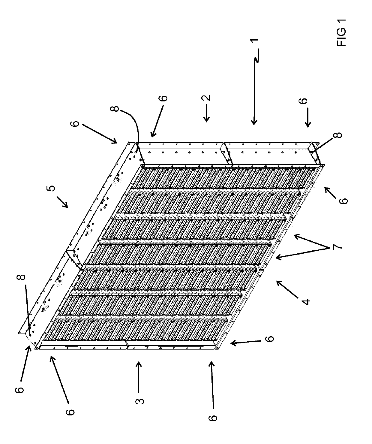
[0008]FIG. 1 shows an embodiment of the blast valve,

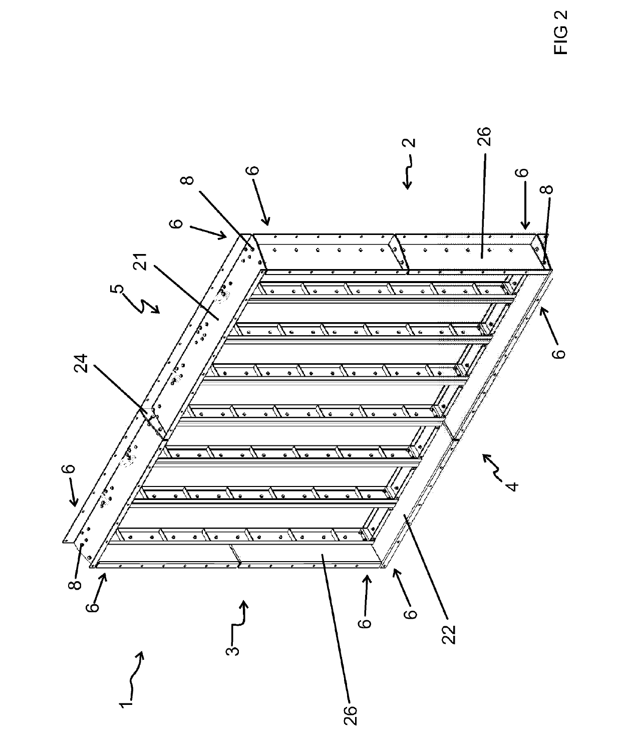
[0009]FIG. 2 shows the frame of the blast valve shown in FIG. 1,

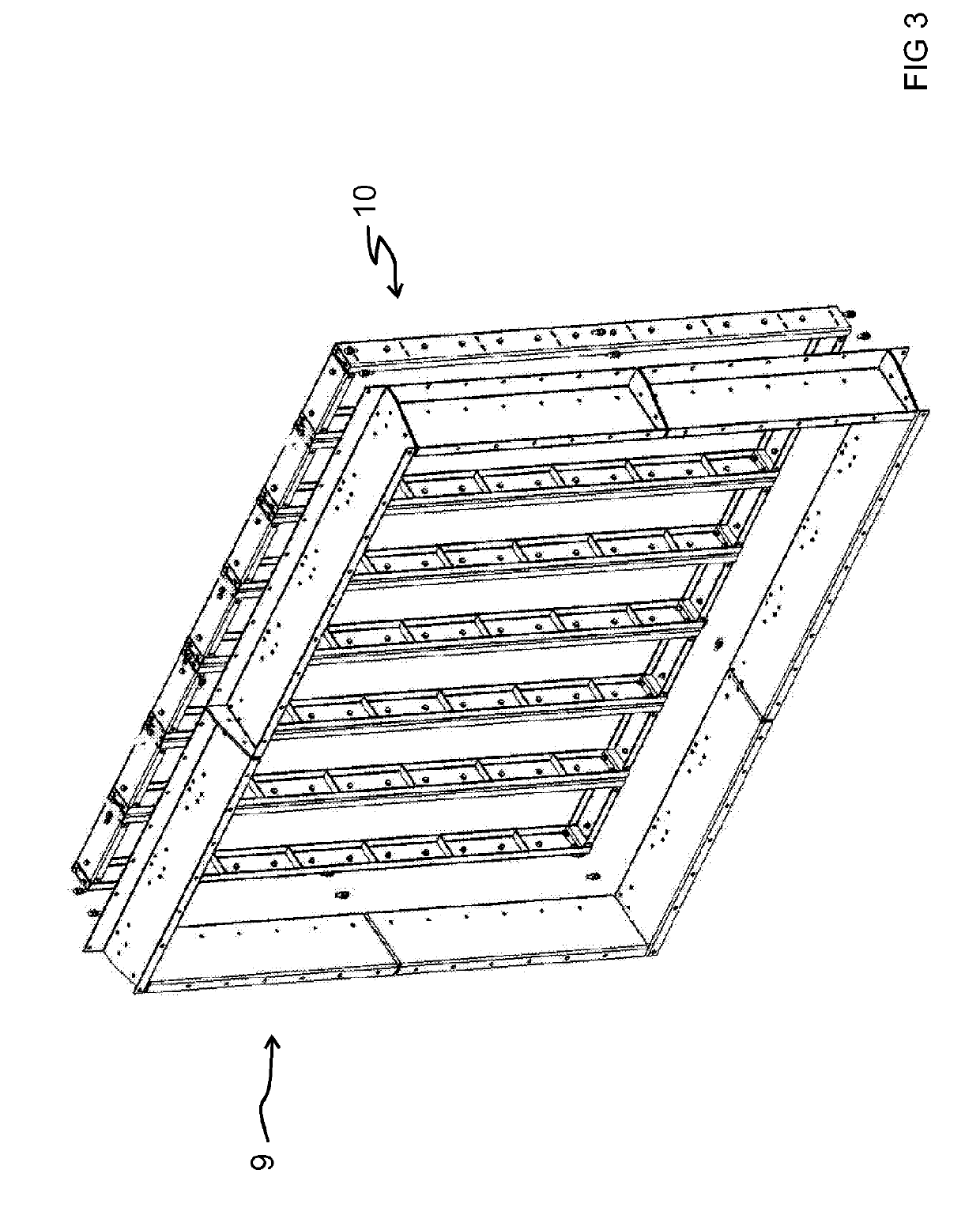
[0010]FIG. 3 is an explosion view of the frame shown in FIG. 2 showing the outer frame and the inner frame separated from each other,

[0011]FIG. 4 shows the inner frame of the frame shown in FIG. 2,

[0012]FIG. 5 shows a frame section of the inner frame shown in FIG. 4,

[0013]FIG. 6 shows the frame section shown in FIG. 5 in a state, where a row of closure devices is arranged in the frame section,

[0014]FIG. 7 shows one of a first vertical beam and second vertical beam of the frame section shown in FIG. 5,

[0015]FIG. 8 shows one of an upper horizontal beam and a lower horizontal beam o...


PUM


Abstract

Described is a blast valve comprising a frame (1) having a first elongated side member (2), a second elongated side member (3), an elongated bottom member (4), and an elongated top member (5). A plurality of parallel rows of closure devices (7) arranged in the frame (1). The first elongated side member (2) being attached to the elongated bottom member (4) and to the elongated top member (5) by external fastening means (8), and the second elongated side member (3) being attached to the elongated bottom member (4) and to the elongated top member (5) by external fastening means (8).

Description

FIELD OF THE INVENTION[0001]The invention relates to a blast valve as defined in the preamble of independent claim 1.[0002]The invention relates especially to blast valves designed for industrial use to protect personnel and critical equipment against blast wave created by an explosion in an industrial facility such as in an oil and / or gas platform or in an oil refinery.[0003]Publication FI 124126 presents a blast valve.[0004]One problem with the blast valve presented in publication FI 124126 is that if the size of the blast valve is large such as if the blast valve comprises over six parallel rows of closure devices each row comprising over ten closure devices, transportation of the blast valve to the mounting site is a problem.OBJECTIVE OF THE INVENTION[0005]The object of the invention is to solve the above identified problem.Short Description of the Invention[0006]The blast valve of the invention is characterized by the definitions of independent claim 1. Preferred embodiments of...

Claims


Application Information

Patent Timeline
IPC IPC(8): A62C2/14F24F11/89F24F13/15
CPCA62C2/14F24F13/15F24F11/89F24F2221/36F16K1/16F16K17/36F16K27/00
Inventor KARKKULAINEN, TIMO
Owner IDG FINANCE S A R L
Why Eureka
Try Eureka