Image forming system

Active Publication Date: 2019-09-05
KONICA MINOLTA INC
View PDF4 Cites 0 Cited by
  • Summary
  • Abstract
  • Description
  • Claims
  • Application Information

AI Technical Summary

Benefits of technology

[0015]Objects of the present invention include correcting strain of a bottom plate of a housing of a

Problems solved by technology

If the image forming apparatus is installed on an uneven floor surface, its housing may incline (strain).
In this case, the strain of the housing may deviate units (a photosensitive drum and so forth) connected to the housing from their positions or put the units under load, which may decrease image quality or damage the image forming apparatus.
Still further, even if the floor surface is flat at the time of the installation, as time elapses, the installation surface could sink by the weight of the image forming apparatus.
However, there may be no space to ensure the rigidity, or it may increase costs.
However, the technology disclosed in JP 2006-

Method used


Image

  • Image forming system
  • Image forming system
  • Image forming system

Examples


Example

Detection Example 1

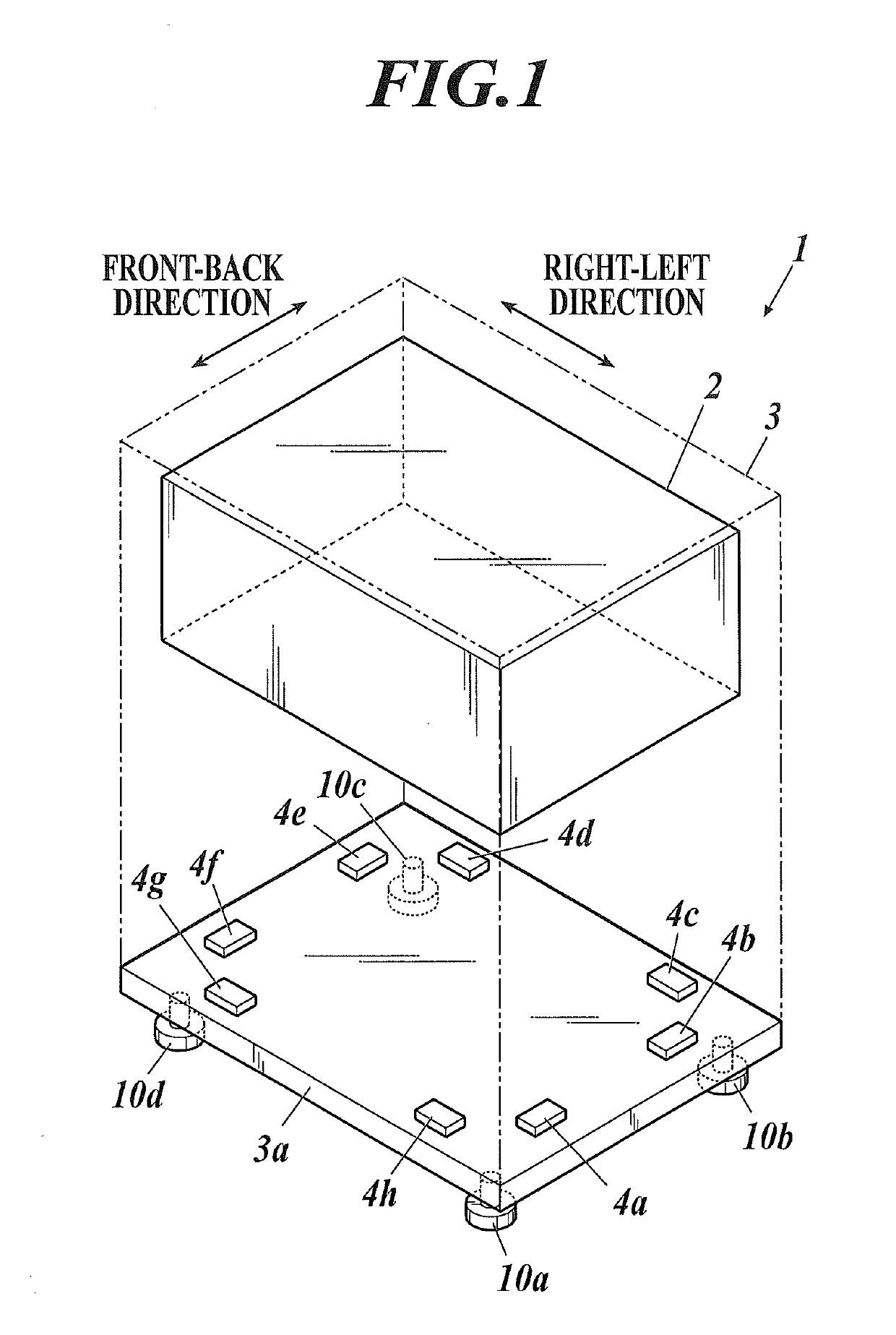
[0081]If the strain occurs in the bottom plate 3a in the right-left direction (the supporting legs 10a and 10b sink) as shown in FIG. 12A and FIG. 12B, voltages of the strain detectors 4d and 4g, which are within spans from the sunk supporting legs 10a and 10b and face (i.e., on the far side from) the supporting legs 10a and 10b, change, and voltages of the other strain detectors 4 do not change. Consequently, the supporting legs 10a and 10b are identified as the adjustment required positions, their adjustment amounts are calculated from the voltage levels, and the supporting legs 10a and 10b are adjusted by the adjustment amounts. Thus, the strain of the bottom plate 3a is solved as shown in FIG. 12C.

Example

Detection Example 2

[0082]If the strain occurs in the bottom plate 3a in the right-left direction and the front-back direction (the supporting leg 10a sinks) as shown in FIG. 13A and FIG. 13B, voltages of the strain detectors 4b and 4g, which are within spans from the sunk supporting leg 10a and face (i.e., on the far side from) the supporting leg 10a, change, and voltages of the other strain detectors 4 do not change. Consequently, the supporting leg 10a is identified as the adjustment required position, its adjustment amount is calculated from the voltage levels, and the supporting leg 10a is adjusted by the adjustment amount. Thus, the strain of the bottom plate 3a is solved as shown in FIG. 13C.

[0083]By reference to the case shown in FIG. 8B and the case shown in FIG. 10A and FIG. 10B, the bottom plate 3a is designed such that deformability thereof is higher at the detection target part(s) for some or all of the strain detectors 4.

[0084]As described above, the adjustment required...


PUM


Abstract

An image forming system includes an image forming apparatus including a housing where an image forming unit is provided and a strain detector, a hardware processor, and a storage. The strain detector detects strain of a bottom plate of the housing. The processor and the storage are included in or provided outside the image forming apparatus. The processor obtains a first detection signal from the detector, stores strain measured data based on the first detection signal as reference data in the storage, obtains a second detection signal from the detector after storing the reference data, compares strain measured data based on the second detection signal with the reference data, and determines whether adjustment of a supporting point height of the bottom plate to reduce the strain due to change over time from a time of the obtainment of the reference data is required.

Description

CROSS REFERENCE TO RELATED APPLICATION[0001]The present application claims priority under 35 U.S.C. § 119 to Japanese Application No. 2018-038144, filed Mar. 5, 2018, the entire contents of which are incorporated herein by reference.BACKGROUND1. Technological Field[0002]The present invention relates to an image forming system.2. Description of the Related Art[0003]There is known an electrophotographic image forming apparatus which irradiates (exposes) a charged photoreceptor with (to) laser light based on image data, thereby forming an electrostatic latent image, develops the formed electrostatic latent image with a toner, thereby forming a toner image, transfers the formed toner image to paper, and fixes the transferred toner image by heat at a fixing unit, thereby forming an image on the paper.[0004]If the image forming apparatus is installed on an uneven floor surface, its housing may incline (strain).[0005]In this case, the strain of the housing may deviate units (a photosensiti...

Claims


Application Information

Patent Timeline
IPC IPC(8): G03G15/00
CPCG03G15/5008G03G15/5004G03G15/5066G03G15/55G03G21/1619G03G2221/1678
Inventor YAMAMOTO, KENICHI
Owner KONICA MINOLTA INC
Why Eureka
Try Eureka