
Vehicle frame structure

a vehicle frame and frame technology, applied in the direction of superstructure connections, superstructure subunits, suspensions, etc., can solve the problems of higher cost of vehicle frame members and the configuration in which vehicle frame members are reinforced by a fiber reinforced plastic member including continuous fibers is more expensive than the configuration in which fibers are oriented. , to achieve the effect of reducing the adhesiveness to be suppressed, reducing the bending rigid

Active Publication Date: 2019-09-19
TOYOTA JIDOSHA KK
View PDF1 Cites 16 Cited by
  • Summary
  • Abstract
  • Description
  • Claims
  • Application Information

AI Technical Summary

Benefits of technology

This patent describes a way to make a stronger vehicle frame without adding much cost or reducing the adhesion between the frame and the reinforcing material. It uses fiber reinforced plastic to reinforce the frame, which can help prevent the frame from getting weaker over time.

Problems solved by technology

Fiber reinforced plastic (FRP) including continuous fibers aligned along an orientation direction is more expensive than FRP including fibers oriented along different directions.
Accordingly, vehicle frame structures in which vehicle frame members are reinforced by a fiber reinforced plastic member including continuous fibers are higher in cost than configurations including fibers oriented along different directions.
However, in configurations employing a fiber reinforced plastic member including randomly oriented fibers, when heating to soften the resin to configure a base member, a greater tendency is seen in an adhesive used to adhere the vehicle frame member and the fiber reinforced plastic member together to be liable to flow than in cases in which a fiber reinforced plastic member including aligned fibers is employed.
The second fiber reinforced plastic member is more expensive than the first fiber reinforced plastic member.

Method used


Image

  • Vehicle frame structure
  • Vehicle frame structure
  • Vehicle frame structure

Examples


first exemplary embodiment

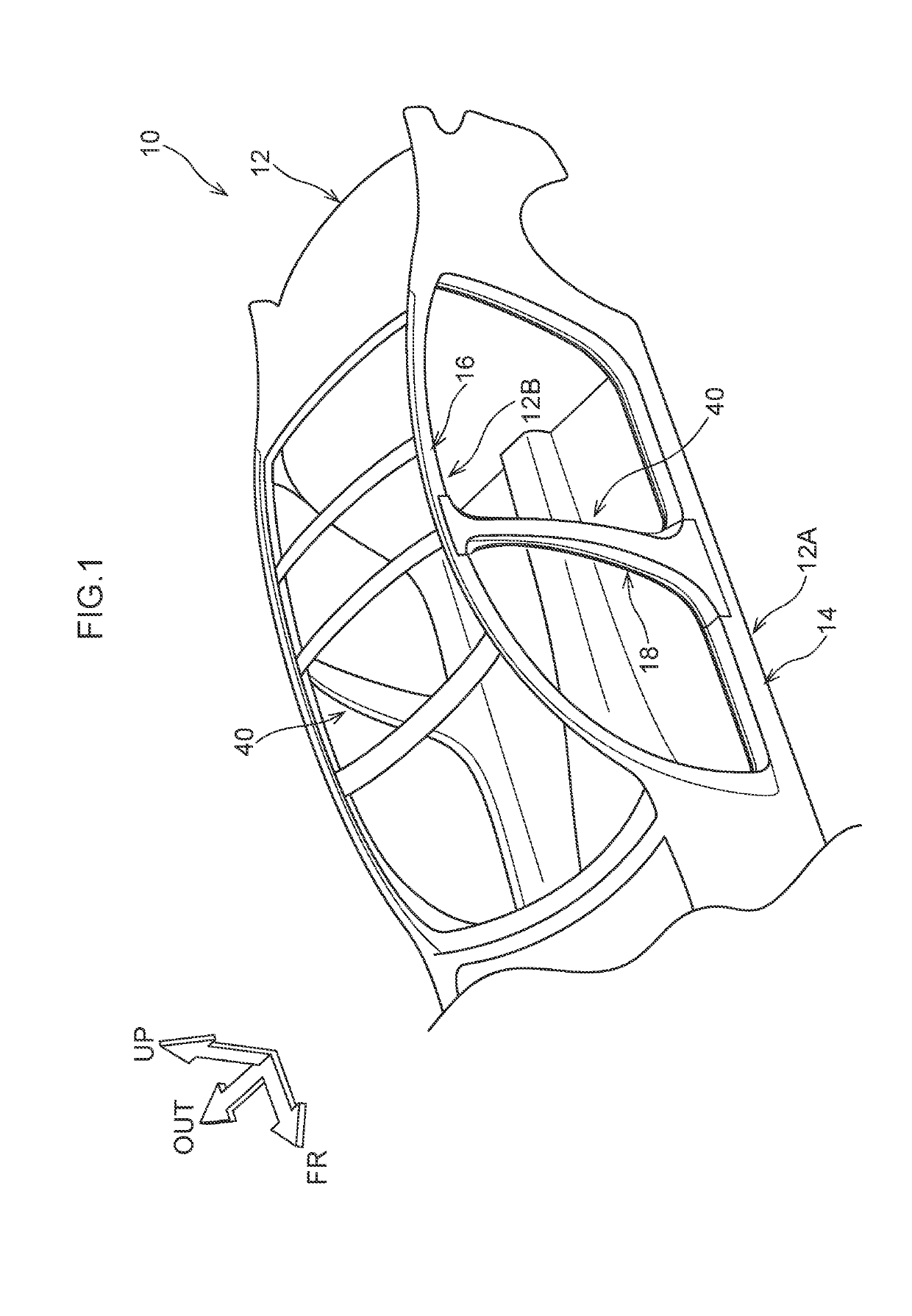
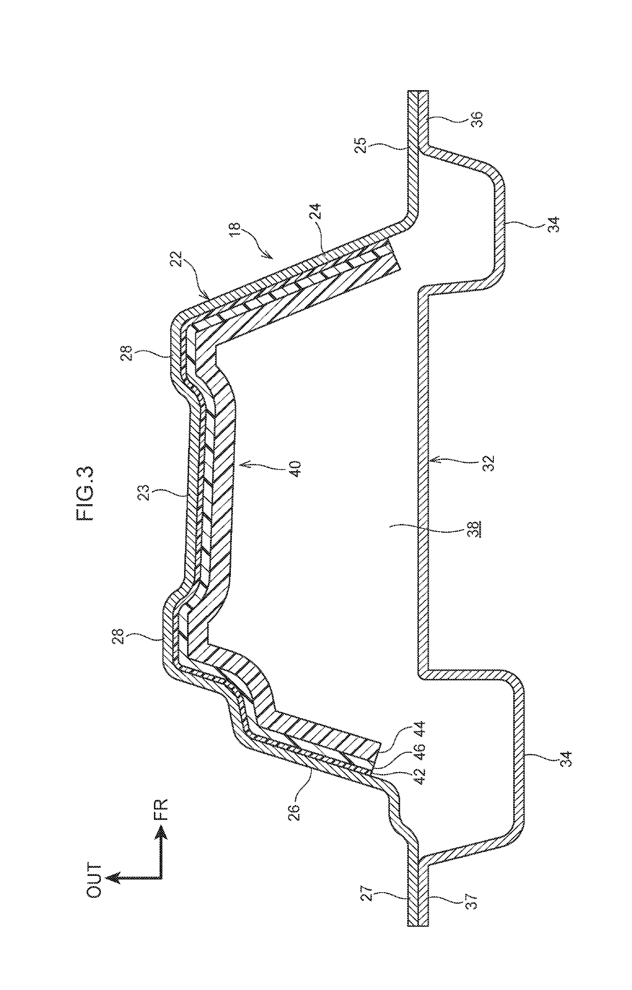
[0047]Explanation follows regarding a vehicle frame structure 40 of a first exemplary embodiment as an example of a vehicle frame structure. Note that in the drawings, the arrow FR points toward the vehicle front (direction of travel), the arrow UP points toward the vehicle upper side, and the arrow OUT points toward a vehicle width direction outer side. In the following explanation, unless specifically stated otherwise, reference to front and rear, upward and downward, and left and right respectively refer to front and rear in a vehicle front-rear direction, upward and downward in a vehicle vertical direction, and left and right in a vehicle width direction when facing the direction of travel.

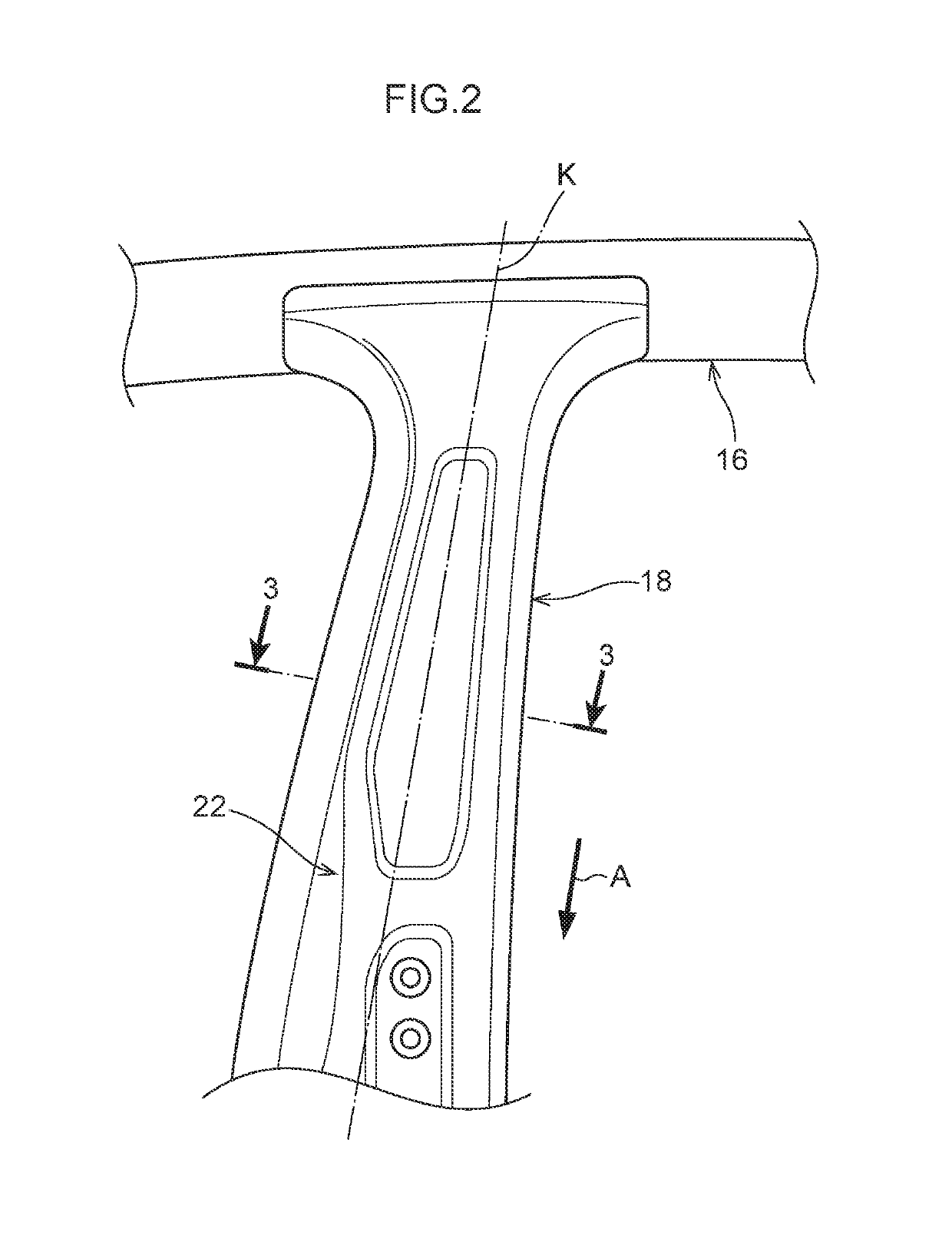
[0048]FIG. 1 illustrates a vehicle body 12 configuring part of a vehicle 10. The vehicle body 12 includes rockers 14, roof side rails 16, and center pillars 18. The vehicle frame structure 40, described later, is applied to the respective center pillars 18.

[0049]Each rocker 14 is provided to a...

second exemplary embodiment

[0094]Explanation follows regarding a vehicle frame structure 60 according to a second exemplary embodiment.

[0095]FIG. 9 illustrates a vehicle frame structure 60 according to the second exemplary embodiment, provided to the vehicle 10 (see FIG. 1) instead of the vehicle frame structure 40 (see FIG. 3). Configurations similar to those of the first exemplary embodiment are allocated the same reference numerals, and explanation thereof is omitted.

[0096]FIG. 9 illustrates a state in which the outer panel 22 is viewed from the vehicle width direction inner side. The outer panel 22 is provided with the vehicle frame structure 60. Note that the vehicle frame structure 60 is provided to the outer panel 22 in a range corresponding to the range S described previously (see FIG. 6). The vehicle frame structure 60 is simplified in FIG. 9.

[0097]As illustrated in FIG. 10, the vehicle frame structure 60 includes the adhesive sheet 42, a first fiber reinforced plastic member 62, and the second fiber...

third exemplary embodiment

[0112]Explanation follows regarding a vehicle frame structure 70 according to a third exemplary embodiment.

[0113]FIG. 11 illustrates the vehicle frame structure 70 according to the third exemplary embodiment, provided to the vehicle 10 (see FIG. 1) instead of the vehicle frame structure 40 (see FIG. 3). Configurations similar to those of the first exemplary embodiment are allocated the same reference numerals, and explanation thereof is omitted.

[0114]FIG. 11 illustrates a state in which the outer panel 22 is viewed from the vehicle width direction inner side. The outer panel 22 is provided with the vehicle frame structure 70. Note that the majority of the range in which vehicle frame structure 70 is provided to the outer panel 22 is within the range S described previously.

[0115]The vehicle frame structure 70 illustrated in FIG. 12 includes the adhesive sheet 42, a first fiber reinforced plastic member 72, and the second fiber reinforced plastic member 46. In other words, the vehicle...


PUM


Abstract

A vehicle frame structure includes: an adhesive member that is superimposed on and adhered to a plate shaped vehicle frame member extending in one direction such that the adhesive member is superimposed in a thickness direction of the vehicle frame member; a first fiber reinforced plastic member that includes plural first fibers oriented in different directions to each other, and that is disposed spaced apart from the vehicle frame member in the thickness direction; and a second fiber reinforced plastic member that includes plural second fibers oriented in an orientation direction of an intersecting direction intersecting the thickness direction, that has a thinner thickness in the thickness direction than a thickness of the first fiber reinforced plastic member, and that is sandwiched between the adhesive member and the first fiber reinforced plastic member in the thickness direction.

Description

CROSS-REFERENCE TO RELATED APPLICATION[0001]This application is based on and claims priority under 35 USC 119 from Japanese Patent Application No. 2018-051166 filed on Mar. 19, 2018, the disclosure of which is incorporated by reference herein.BACKGROUNDTechnical Field[0002]The present disclosure relates to a vehicle frame structure.Related Art[0003]Japanese Patent Application Laid-Open (JP-A) No. 2015-160524 discloses a vehicle body structure in which a carbon fiber reinforced plastic (CFRP) reinforcement member is adhered to a vehicle width direction inner wall of a metal B-pillar (center pillar). The reinforcement member includes a layer of continuous carbon fibers that are oriented along the length direction of the B-pillar, the layer having a thickness of at least 0.8 mm.[0004]Fiber reinforced plastic (FRP) including continuous fibers aligned along an orientation direction is more expensive than FRP including fibers oriented along different directions. Accordingly, vehicle frame...

Claims


Application Information

Patent Timeline
Patent Type & Authority Applications(United States)
IPC IPC(8): B62D21/02B62D29/00B62D29/04B62D27/02
CPCB62D29/005B62D29/043B62D27/02B62D29/048B60G2206/7101B62D21/02B62D25/04B62D27/026B62D29/00B62D25/025B62D25/06B62D25/02B62D25/20
Inventor KUROKAWA, HIROYUKI
Owner TOYOTA JIDOSHA KK
Learn More