
Device and Method of Gear Noise Reduction

Active Publication Date: 2019-10-17
1 UP DESIGN & CONSULTING LLC
View PDF0 Cites 4 Cited by
  • Summary
  • Abstract
  • Description
  • Claims
  • Application Information

AI Technical Summary

Benefits of technology

The present invention can be applied to existing gears by removing material in the distal end of the gear teeth. This modification allows for improved load sharing between two teeth, even if there is some pitch error. This can lead to reduced transmission error, decreased sensitivity to pitch error, and smoother load transition. Overall, this invention provides a way to improve the performance of gear systems in a variety of applications.

Problems solved by technology

The major source of gear noise is transmission error, which is a violation of the fundamental principle of gearing.
Deviations from the ideal involute shape are a source of transmission error, but even with a perfectly manufactured gear, variations in stiffness are still present.
These loads are often transmitted to the gearbox or housing, further increasing the noise.
However, crowning is directed to reducing edge contact due to misalignment and other gear manufacturing and mounting errors.
In other words, crowning fails to modify the gear mesh stiffness variation present.
Conventional methods to reduce noise are typically related to different shapes of crowning to reduce noise, but such methods only address the stiffness associated with the contact area and fail to address the bending stiffness of the whole tooth.

Method used


Image

  • Device and Method of Gear Noise Reduction
  • Device and Method of Gear Noise Reduction
  • Device and Method of Gear Noise Reduction

Examples


Embodiment Construction

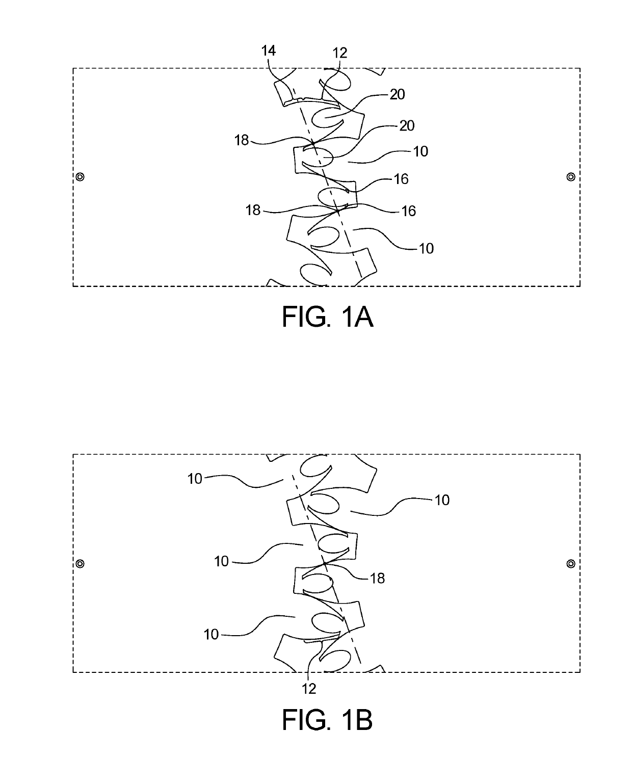
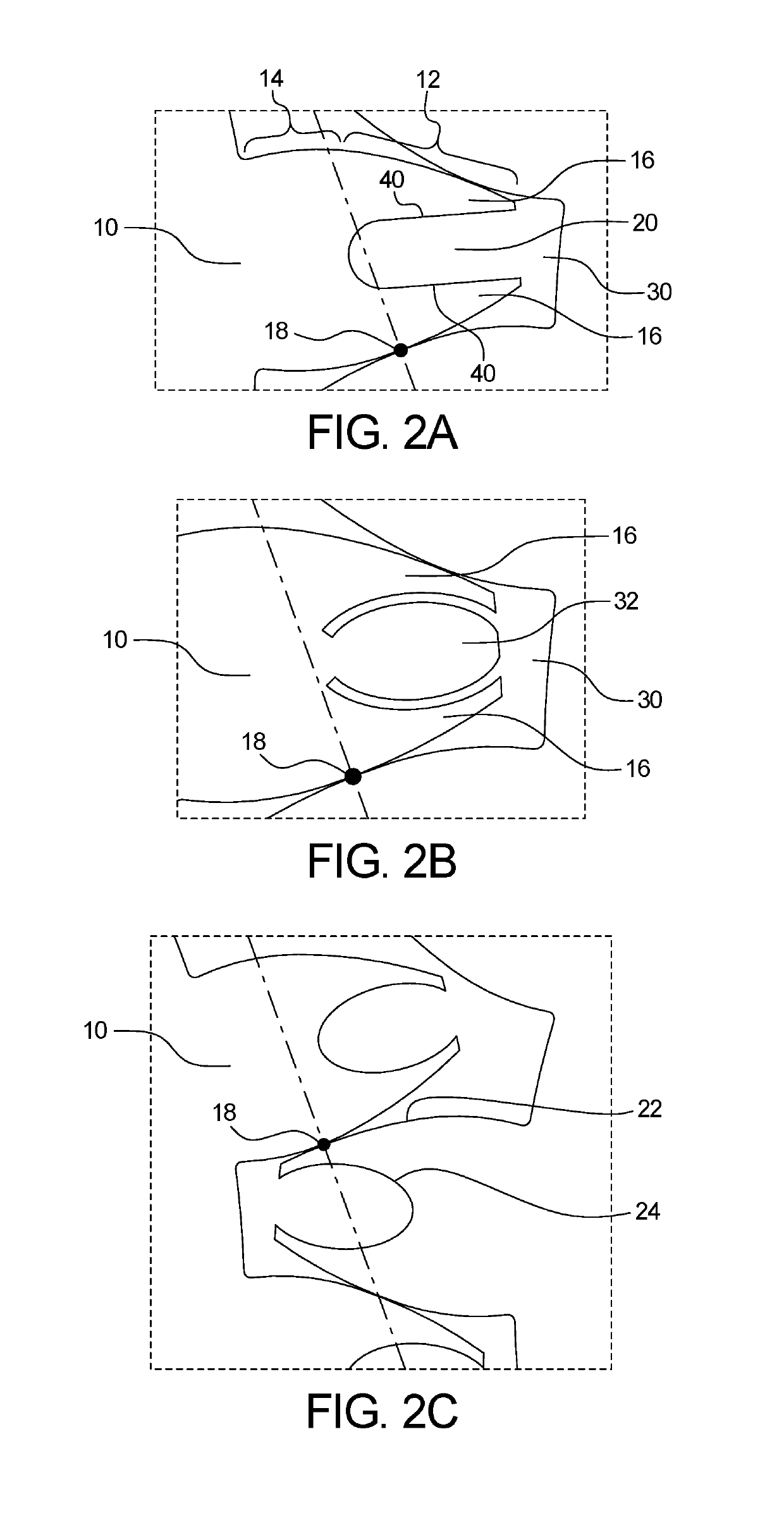
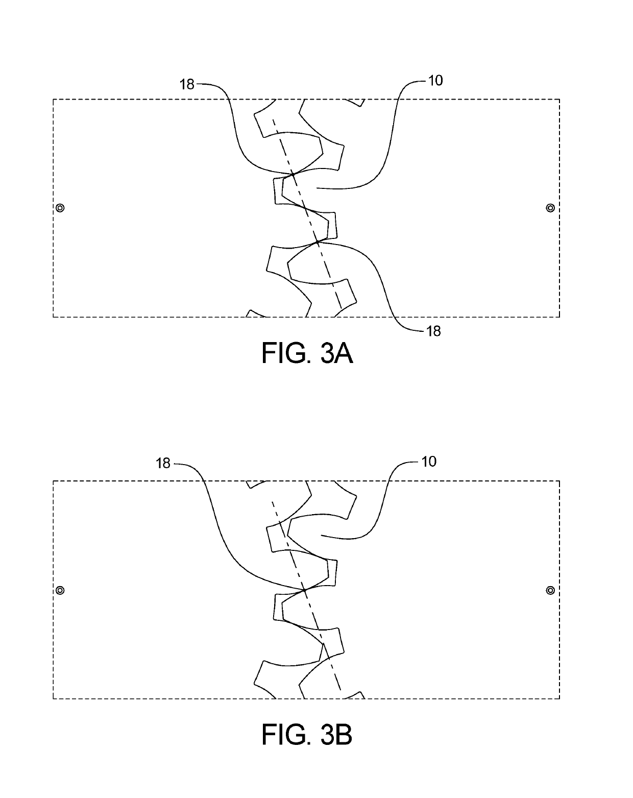
[0023]The present invention is directed to a device including gears with bending compliance in the outer portion of the gear tooth to reduce gear noise. The present device reduces the variation in gear stiffness by introducing bending compliance in the outer portion of the gear tooth, by way of a cutout or relief area from the end of the tooth.

[0024]Noise is often reverberated from the housing or gearbox as the loads are transmitted through the shafts and bearings. In the present device, stiffness matching is achieved by decreasing the stiffness of the gear tooth near the tip. This is primarily to counteract the increase in stiffness when there are two pairs of gear teeth in contact simultaneously. The stiffness is reduced by a specific amount and can match the stiffness as when only one pair of teeth is in contact. The gradual reduction in stiffness in the departing tooth pair coincides with an increasing stiffness of the next tooth pair and will smooth the transition of the load f...


PUM


Abstract

The present device includes gears with bending compliance in the outer portion of the gear teeth to reduce gear noise. The present device reduces the variation in gear stiffness by introducing bending compliance in the outer portion of the gear tooth, by way of a cutout or relief area in the distal end of the tooth.

Description

CROSS-REFERENCE TO RELATED APPLICATIONS[0001]This application incorporates by reference and claims the benefit of priority to U.S. Provisional Application 62 / 657,282 filed on Apr. 13, 2018.BACKGROUND OF THE INVENTION[0002]The present disclosure relates to mechanical gears. More specifically, the present disclosure relates to a method of reducing gear noise by the addition of bending compliance in the outer portion of gear teeth.[0003]The major source of gear noise is transmission error, which is a violation of the fundamental principle of gearing. The principle states that the ratio of the rotational speeds of the geared shafts must be constant. The involute profile is the mathematically derived ideal shape to achieve this goal, but it is based on rigid bodies. Deviations from the ideal involute shape are a source of transmission error, but even with a perfectly manufactured gear, variations in stiffness are still present. Such variation in stiffness is due to the elasticity of the ...

Claims


Application Information

Patent Timeline
IPC IPC(8): F16H57/00F16H55/16F16H55/17
CPCF16H55/17F16H55/16F16H57/0006
Inventor ELDER, JOSHUA TYLER
Owner 1 UP DESIGN & CONSULTING LLC
Learn More