
Spinal constructs with improved load-sharing

Active Publication Date: 2012-03-01
WARSAW ORTHOPEDIC INC
View PDF1 Cites 11 Cited by
  • Summary
  • Abstract
  • Description
  • Claims
  • Application Information

AI Technical Summary

Benefits of technology

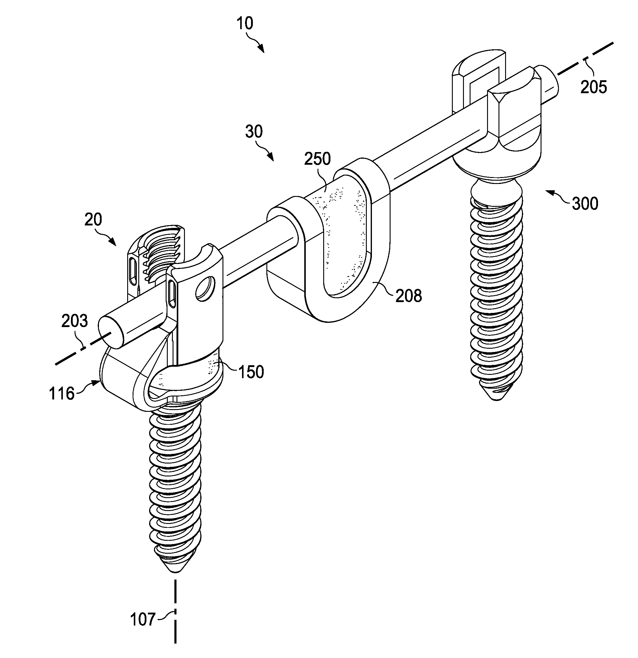
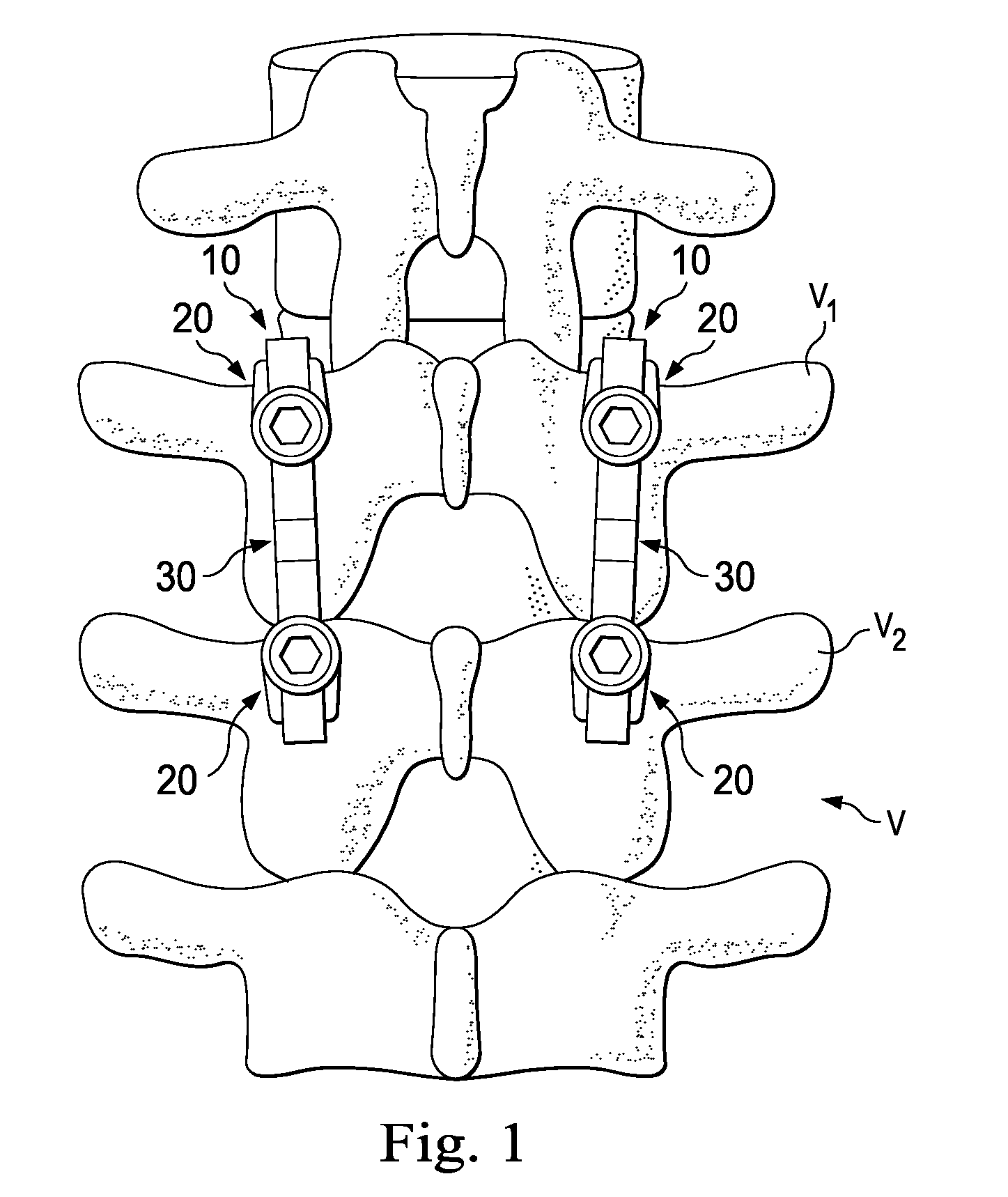
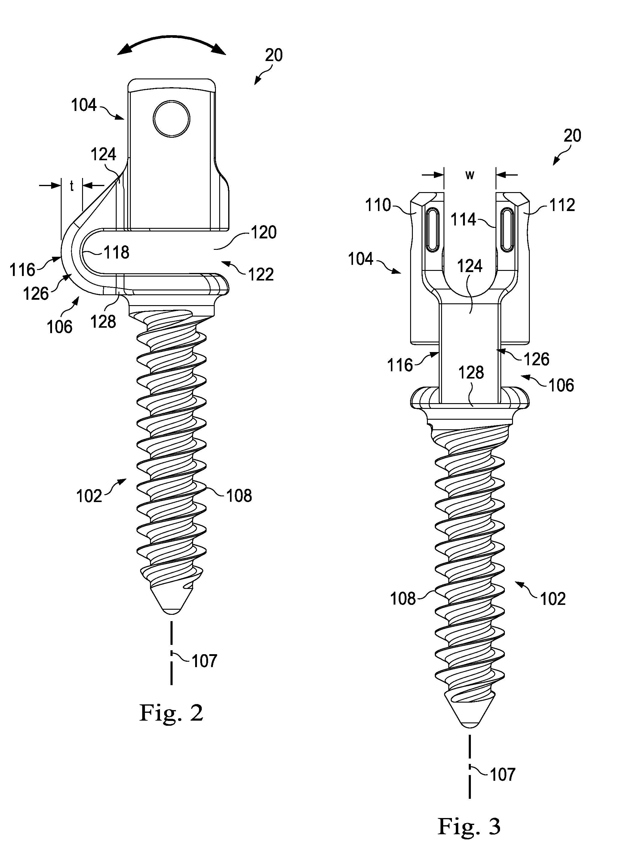
[0006]In one exemplary aspect the present disclosure is directed to a spinal construct for implantation in a patient to provide stabilization to spinal structure with improved load sharing. The construct includes a flexible spinal rod having a first end and a second end, the spinal rod being configured to provide stabilization to spinal structure. It also includes a first bone fastener configured to securely attach to the flexible spinal rod and a second bone fastener configured to securely attach to the flexible spinal rod. The second bone fastener is a dynamic fastener arranged to provide motion in one direction more than another direction. The flexible spinal rod and the second bone fastener are oriented to cooperate in a manner that achieves load sharing by dynamically flexing under applied loads in a manner that distributes stresses and strains between the flexible spinal rod and the second bone fastener.
[0007]In some aspects, the first bone fastener comprises a dynamic fastener arranged to provide motion in one direction more than another direction. The flexible spinal rod, the first bone fastener, and the second bone fastener are oriented to cooperate in a manner that achieves load sharing by dynamically flexing under applied loads in a manner that distributes stresses and strains between the flexible spinal rod and both the first and the second bone fasteners.
[0009]In another exemplary aspect, the present disclosure is directed to a spinal construct for implantation in a patient to provide stabilization to spinal structure with improved load sharing. The construct includes a flexible spinal rod having a first end and a second end, and being configured to provide stabilization to spinal structure. The spinal rod is configured in a manner that provides relatively more motion in a flexion and extension direction and relatively less motion in a lateral direction. The construct also includes a first bone fastener configured to securely attach to the flexible spinal rod. The first bone fastener being configured in a manner that provides relatively more motion in a flexion and extension direction and relatively less motion in a lateral direction. The flexible spinal rod and the first bone fastener are oriented to cooperate in a manner that achieves load sharing by dynamically flexing under applied loads in a manner that distributes stresses and strains between the flexible spinal rod and the first bone fastener.

Problems solved by technology

Spinal disorders typically result in symptoms including pain, nerve damage, and partial or complete loss of mobility.
Non-surgical treatments, such as medication, rehabilitation and exercise can be effective, however, may fail to relieve the symptoms associated with these disorders.

Method used


Image

  • Spinal constructs with improved load-sharing
  • Spinal constructs with improved load-sharing
  • Spinal constructs with improved load-sharing

Examples


Embodiment Construction

[0022]The present disclosure relates generally to the field of implantable bone stabilization constructs, and more particularly to constructs having at least one dynamic bone fastener and a dynamic rod that cooperate together to achieve load sharing while providing stabilizing support to bone structure and tissue. For the purposes of promoting an understanding of the principles of the invention, reference will now be made to embodiments or examples illustrated in the drawings, and specific language will be used to describe these examples. It will nevertheless be understood that no limitation of the scope of the invention is thereby intended. Any alteration and further modifications in the described embodiments, and any further applications of the principles of the invention as described herein are contemplated as would normally occur to one skilled in the art to which the disclosure relates.

[0023]The exemplary embodiments of the bone stabilization constructs are configured to provid...


PUM


Abstract

A spinal construct for implantation in a patient to provide stabilization to spinal structure with improved load sharing includes a flexible spinal rod having a first end and a second end, the spinal rod being configured to provide stabilization to spinal structure. It also includes a first bone fastener configured to securely attach to the flexible spinal rod and a second bone fastener configured to securely attach to the flexible spinal rod. The second bone fastener is a dynamic fastener arranged to provide motion in one direction more than another direction. The flexible spinal rod and the second bone fastener are oriented to cooperate in a manner that achieves load sharing by dynamically flexing under applied loads in a manner that distributes stresses and strains between the flexible spinal rod and the second bone fastener.

Description

FIELD OF THE INVENTION[0001]The present disclosure is directed to stabilization constructs, and more particularly, to stabilization constructs with improved load sharing.BACKGROUND[0002]Spinal disorders such as degenerative disc disease, disc herniation, osteoporosis, spondylolisthesis, stenosis, scoliosis and other curvature abnormalities, kyphosis, tumor, and fracture may result from factors including trauma, disease and degenerative conditions caused by injury and aging. Spinal disorders typically result in symptoms including pain, nerve damage, and partial or complete loss of mobility.[0003]Non-surgical treatments, such as medication, rehabilitation and exercise can be effective, however, may fail to relieve the symptoms associated with these disorders. Surgical treatment of these spinal disorders include discectomy, laminectomy, fusion and implantable prosthetics. As part of these surgical treatments, spinal constructs such as vertebral rods are often used to provide stability ...

Claims


Application Information

Patent Timeline
IPC IPC(8): A61B17/70
CPCA61B17/7026A61B17/7032A61B17/7031A61B17/7004A61B17/7011A61B17/7019A61B17/7035
Inventor TRIEU, HAI H.HARMON, JON A.
Owner WARSAW ORTHOPEDIC INC
Learn More