
Bicycle crank

Inactive Publication Date: 2011-01-20
LEE CHEN HSIAO
View PDF6 Cites 7 Cited by
  • Summary
  • Abstract
  • Description
  • Claims
  • Application Information

AI Technical Summary

Benefits of technology

[0009]A primary objective of the invention is to provide a bicycle crank, wherein its L-shaped crank is integrally composed of a crank and a connection head to improve the product quality and to achieve solid and durable condition and may not be easily broken. In addition, a compression shaft, a cone shaped member, and locking members are mutually incorporated to ensure that the L-shaped crank can approach the center place of a sleeve to stabilize the entire structure.

Problems solved by technology

Since modern people are very busy, most of them always drive cars for their duties in hurry and are unable to enjoy any leisure activity for relaxing pressures resulted from works.
Consequently, the pedals connected to the crank structure cannot be smoothly stepped on or may become rusty or be easily broken, and furthermore the crank structure may endanger the user safety due to worse material quality.
The shortcomings of the publication structure are shown as the following:1. Corresponding insides of the first and second rotary sleeves must be processed to produce wave teeth so that slip and idle running may not happen after the two part are assembled, thus consequently causing complicated processing procedure and high manufacturing cost.2. Further, the goal of integrally connecting the first and second rotary sleeves may be achieved by means of mutually locking the first and second nuts and the screw bolts, thus causing many assembly components, time consuming and strenuous effort in installation.3. The connection portion of the side of the first crank connected to the inside of the corresponding side of the first rotary sleeve and the connection portion of the second crank connected to the inside of the corresponding side of the second rotary sleeve adopt the fitting way.
Consequently, it may still cause inaccurate connection.
The crankset assembly may come off the bicycle to increase the potential dangers once the bicycle often passes through bumpy roads.

Method used


Image

  • Bicycle crank
  • Bicycle crank
  • Bicycle crank

Examples


Embodiment Construction

[0017]Other features and advantages of the present invention will become apparent from the following description of the invention which refers to the accompanying drawings.

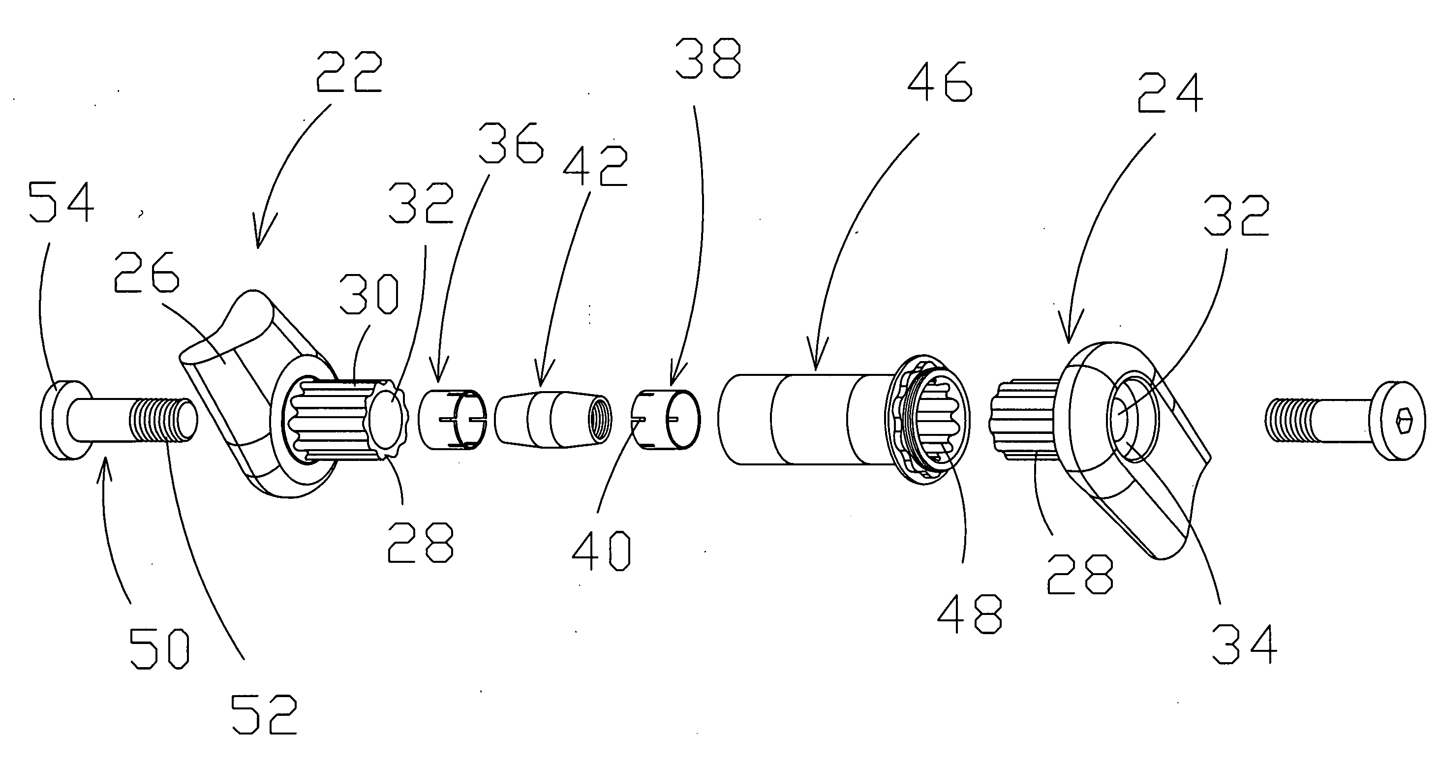
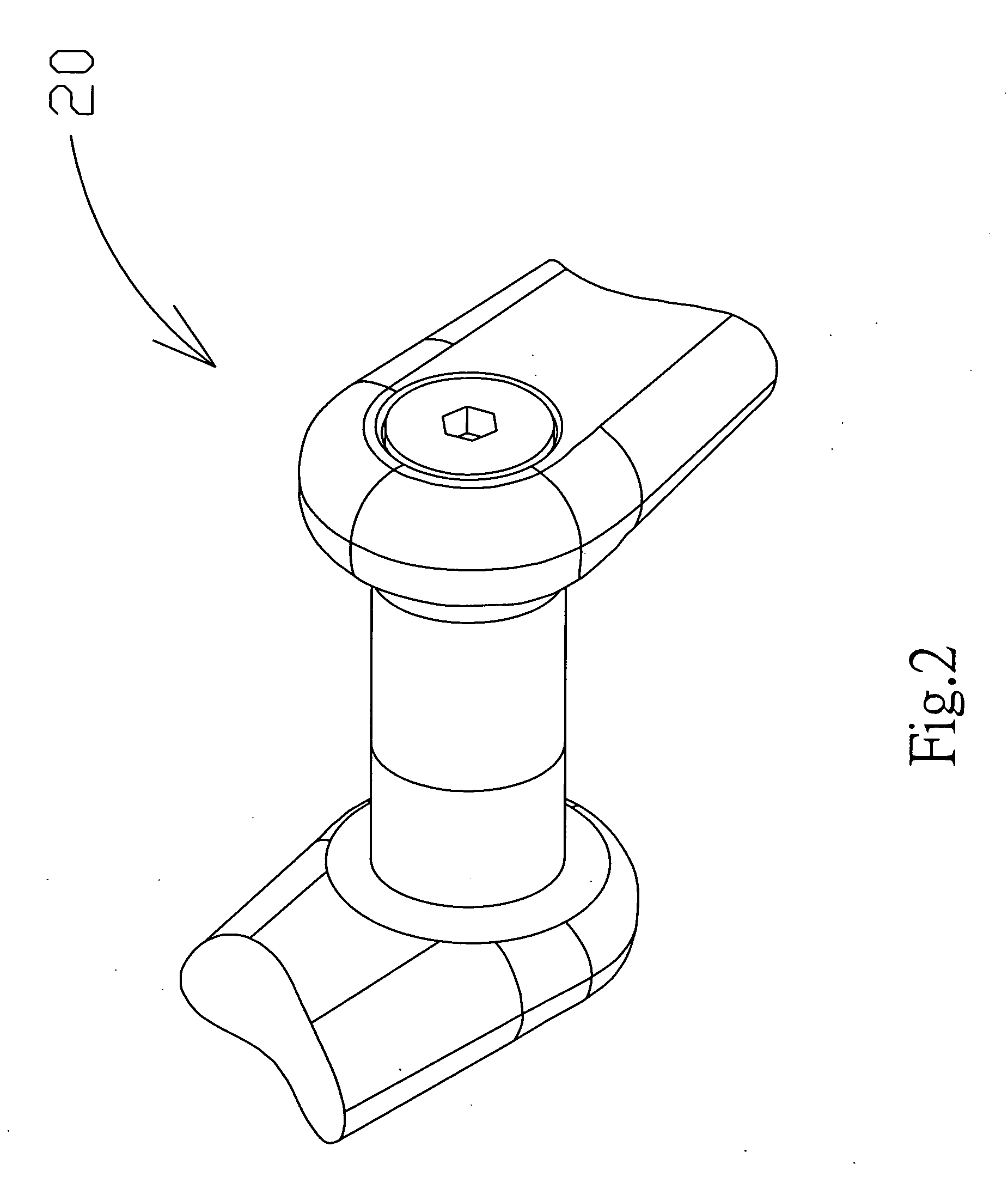
[0018]Please refer to FIG. 2 to FIG. 6, a three-dimensional diagram, a decomposition drawing, a decomposed cross-sectional view, assembly drawings are respectively shown according to an embodiment of the invention.

[0019]Firstly, as shown in the figures, the bicycle crank 20 of the invention comprises an L-shaped left crank 22 and an L-shaped right crank 24 which are symmetrical. Every L-shaped left crank 22 and the L-shaped right crank 24 comprise a crank 26 and a connection head 28 connected to one end of the crank 26. The crank 26 and the connection head 28 are integrally formed. Another end of the crank 26 is connected to a pedal (not shown in the figure). In addition, an outer periphery of the connection head 28 is a first polygonal cloud portion 30.

[0020]Moreover, every L-shaped left crank 22 and the L-shaped...


PUM


Abstract

A bicycle crank comprises an L-type left crank and an L-type right crank. The L-type left / right cranks are respectively and integrally composed of a crank and a connection head, and includes a through hole passing through the crank and the connection head, a left compression shaft and a right compression shaft respectively disposed to terminals of the through holes of the L-type left / right cranks, a cone shaped member in which two ends are respectively disposed in the left and right compression shafts and the inner surface has screw threads, a rotary sleeve that is a hollow and integrally formed, and two locking members in which a terminal has screw threads corresponding to the cone shaped member and for respectively passing through the through holes and locked to two ends of the cone shaped member to connect the L-type left crank and the L-type right crank.

Description

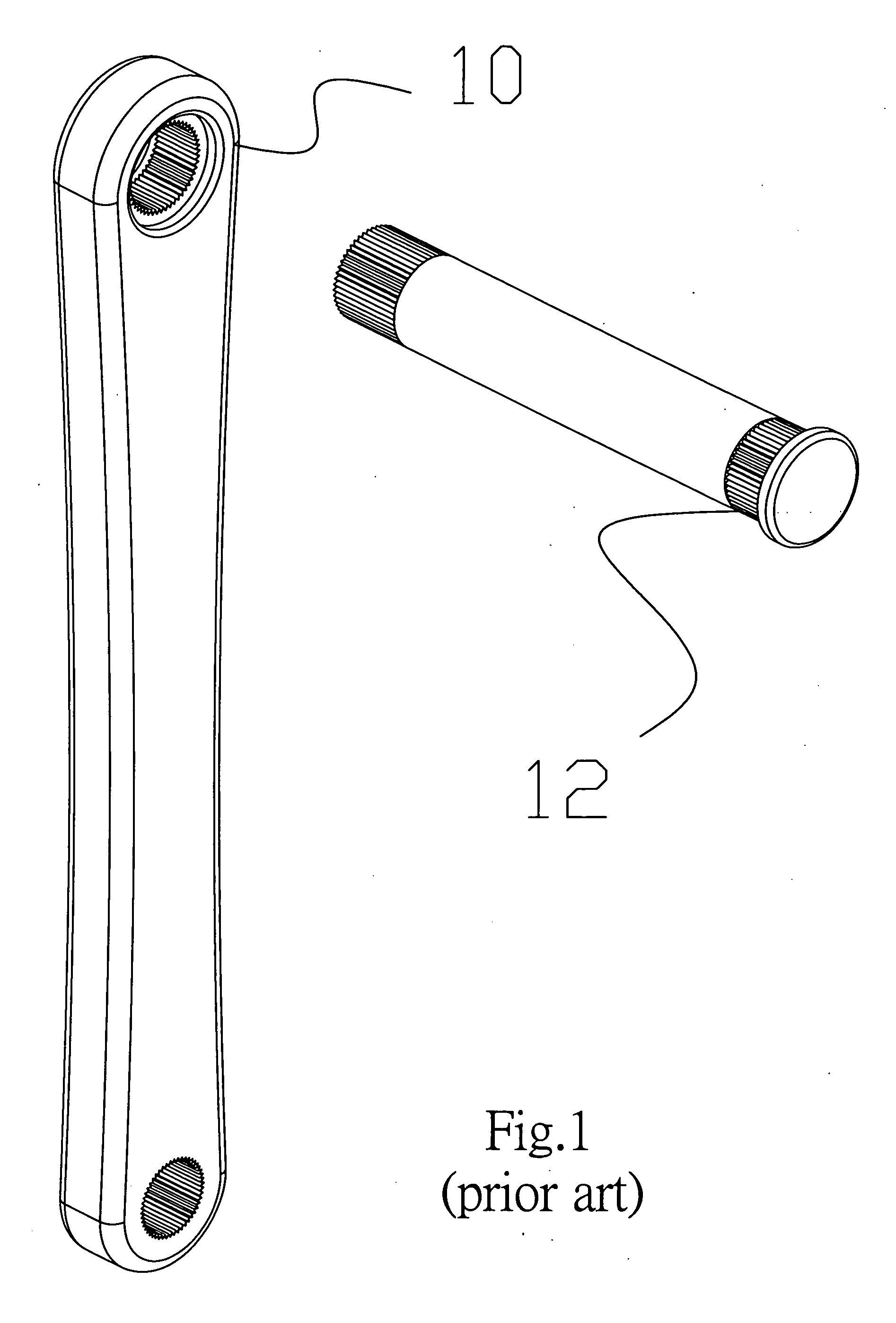
FIELD OF THE INVENTION[0001]The invention relates to a bicycle crank, and more particularly to a bicycle crank that is integrally composed of an L-shaped left crank and an L-shaped right crank incorporated with compression shafts, a cone shaped member and locking members to achieve the bicycle crank having rigidity and durable effect, and a stable entire structure without easily breaking.BACKGROUND OF THE INVENTION[0002]Since modern people are very busy, most of them always drive cars for their duties in hurry and are unable to enjoy any leisure activity for relaxing pressures resulted from works. Nevertheless, everybody gradually recognizes the importance of leisure activities on health. Many outdoor scenic spots develop cycling. Bicycles have played an important role in outdoor activities for leisure exercises.[0003]However, a conventional bicycle crank adopts connection manner. As shown in FIG. 1, a schematic diagram of a conventional bicycle crank structure is shown. The convent...

Claims


Application Information

Patent Timeline
IPC IPC(8): B62M3/00B62M1/36
CPCB62M3/00Y10T74/2164B62M3/003
Inventor LIN, SHENG-YUAN
Owner LEE CHEN HSIAO
Learn More