Handheld symbol reader with optical element to redirect central illumination axis

a technology of central illumination and optical element, which is applied in the direction of instruments, sensing record carriers, sensing by electromagnetic radiation, etc., can solve the problems of lens magnifying the light emitted by illumination sources, image assembly may not obtain a suitable image of barcodes or other symbols, and oversaturation of all or parts of barcodes

Active Publication Date: 2019-10-17
ZEBRA TECH CORP
View PDF2 Cites 8 Cited by
  • Summary
  • Abstract
  • Description
  • Claims
  • Application Information

AI Technical Summary

Problems solved by technology

As a result, the imaging assembly may not obtain a suitable image of the barcode or other symbol, as the barcode is not properly or uniformly illuminated, or barcode is entirely or partially outside the FOV of the imaging assembly.
However, the lens magnified the light emitted by the illumination source.
This had the effect of magnifying the brightest spots of the illumination source (i.e., hotspots) on the barcode, which, in turn, caused oversaturation of all or part of the barcode thereby degrading the quality of the captured image of the barcode.

Method used


Image

  • Handheld symbol reader with optical element to redirect central illumination axis
  • Handheld symbol reader with optical element to redirect central illumination axis
  • Handheld symbol reader with optical element to redirect central illumination axis

Examples


Embodiment Construction

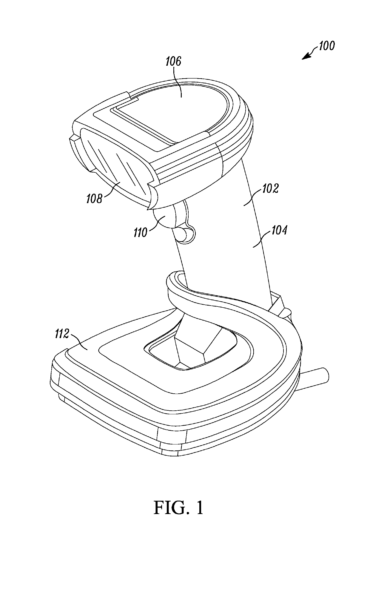
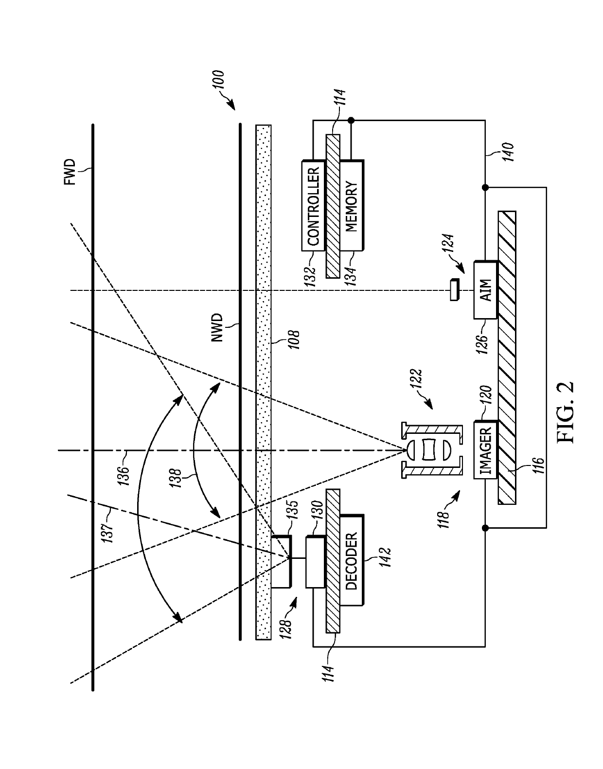
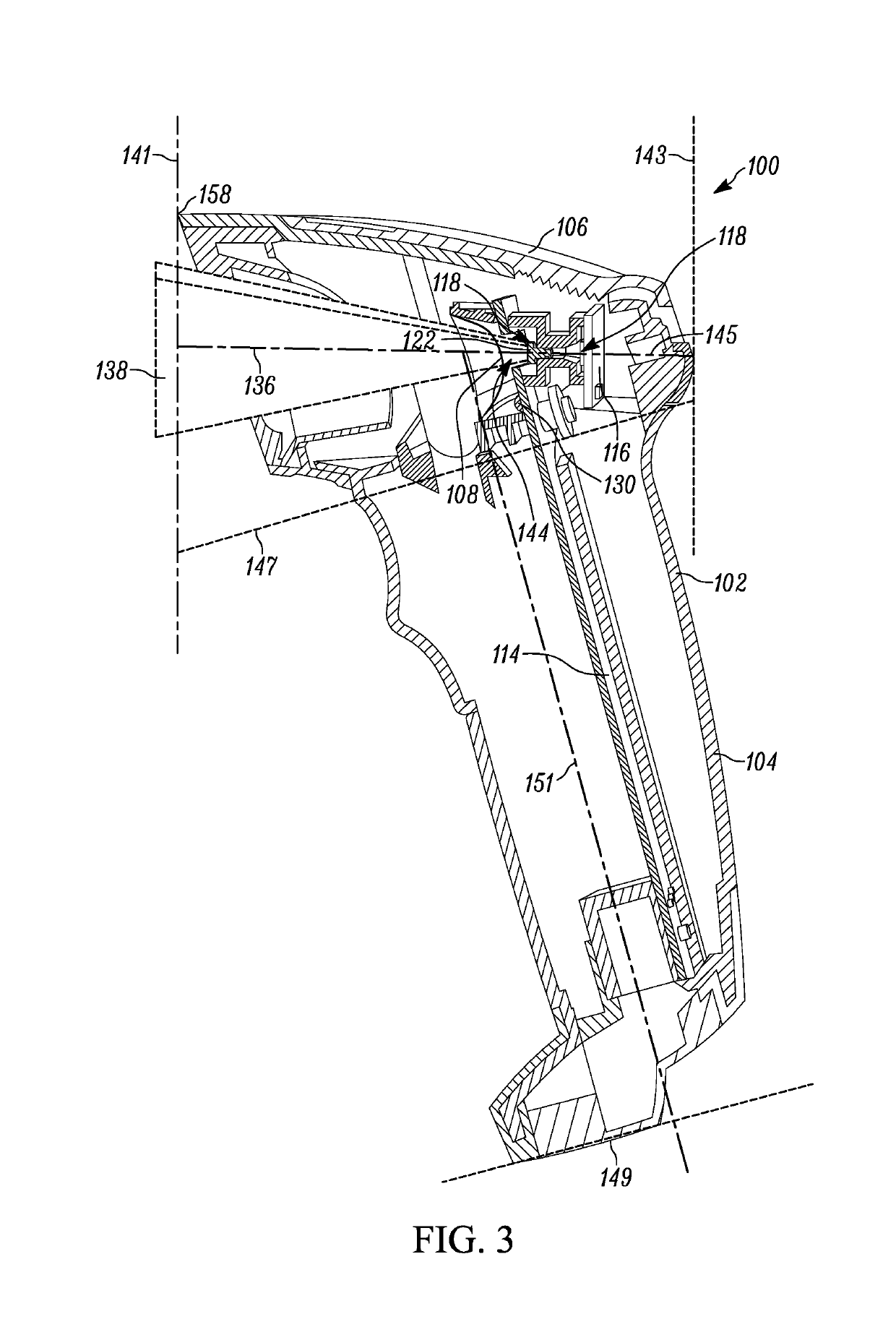
[0014]One aspect of the present disclosure provides an apparatus that includes a housing, an imaging assembly, an illumination assembly and an optical element. The imaging assembly is positioned within the housing and includes an image sensor having a plurality of photosensitive elements forming a substantially flat two-dimensional surface. The image sensor has a field of view (FOV), and the FOV having a central FOV axis. The image sensor is configured to capture either light reflected from a target and light emitted from the target. The illumination assembly is positioned within the housing and configured to emit light having a central illumination axis. The central illumination axis at the point of the illumination assembly is non-parallel to the central FOV axis. The optical element is positioned within the housing and adapted to redirect the central illumination axis towards the central FOV axis at a surface. The optical element provides an optical magnification of less than 1.5...


PUM


Abstract

An apparatus and assembly for redirecting the central illumination axis of an illumination assembly towards the central field of view (FOV) axis of an imaging assembly using an optical element that provides an optical magnification of less than 1.5×, where the central illumination axis at the point of the illumination assembly is non-parallel to the central FOV axis.

Description

BACKGROUND OF THE INVENTION[0001]In some barcode readers, the central illumination axis of light emitted by the illumination source is nonparallel with the central field-of-view (FOV) axis of the imaging assembly. As a result, the imaging assembly may not obtain a suitable image of the barcode or other symbol, as the barcode is not properly or uniformly illuminated, or barcode is entirely or partially outside the FOV of the imaging assembly. Past barcode readers have addressed this problem by placing a lens in front of the illumination source to redirect the central illumination axis. However, the lens magnified the light emitted by the illumination source. This had the effect of magnifying the brightest spots of the illumination source (i.e., hotspots) on the barcode, which, in turn, caused oversaturation of all or part of the barcode thereby degrading the quality of the captured image of the barcode.[0002]Accordingly, there is a need for a barcode reader with an optical element to...

Claims


Application Information

Patent Timeline
Patent Type & Authority Applications(United States)
IPC IPC(8): G06K7/10
CPCG06K2007/10524G06K7/10732G06K7/10881G06K7/10831G06K7/10722G02B27/0972G02B19/0061
Inventor DRZYMALA, MARKBARKAN, EDWARDVINOGRADOV, IGOR
Owner ZEBRA TECH CORP
Why Eureka
Try Eureka