Gas flow arrestor

a technology of gas flow arrestor and gas flow, which is applied in the direction of respirator, functional valve type, container discharging method, etc., can solve the problems of accidental oxygen discharge, more severe safety incidents, and serious safety hazards

Active Publication Date: 2019-11-14
PRAXAIR TECH INC
View PDF0 Cites 0 Cited by
  • Summary
  • Abstract
  • Description
  • Claims
  • Application Information

AI Technical Summary

Benefits of technology

[0007]The present invention may be characterized as a gas flow arrestor device comprising: (i) a main body section defining a first proximal end and having an inlet configured to receive a flow of a gas from a valve integrated pressure regulator (VIPR) associated with a compressed gas cylinder or an oxygen concentrator; (ii) a forward body section defining a distal end and having an outlet configured to deliver the flow of the gas to a patient or a breathing apparatus, such as a nasal cannula or breathing mask; (iii) an internal flow path fluidically coupling the inlet to the outlet; (iv) a sealing member disposed in the internal flow path and configured to allow the gas to flow from the inlet to the outlet when the gas flow arrestor device is in an open position and to prevent the gas to flow from the inlet to the outlet when the gas flow arrestor device is in a closed position; (v) a spring configured for biasing the sealing member within the internal flow path; (vi) a firebreak having a fusible stop disposed along the internal flow path, the firebreak configured to move the sealing member such that the gas flow arrestor device is in the closed position upon fusing of the stop; and (vii) a visual flow indicator that is actuated by the flow of gas along the internal flow path from the inlet to the outlet, the visual flow indicator configured to have a first display when the gas is not flowing along the internal flow path from the inlet to the outlet and at least a second display, different from the first display, when the gas is flowing along the internal flow path from the inlet to the outlet. The fusible stop is preferably made of a plastic material that has a melting point less than that of the material of the main body section, the forward body section, and the flexible tube or hose connected to the forward body section.

Problems solved by technology

Several distinct problems have been identified with the prior art medical oxygen cylinders having VIPR devices integrated therewith.
In the case of a fire that is initiated at or near the patient such as by means of a lit cigarette or lighter, the flame can propagate along the plastic breathing apparatus and hose back to the compressed gas cylinder or oxygen source potentially leading to more severe safety incidents.
Additional problems associated with compressed gas cylinders configured to deliver medical oxygen via a VIPR device relate to oxygen flow indication.
Failure of the user to close the compressed gas cylinder by turning the flow selection knob back to zero flow or a ‘closed’ position, could lead to accidental oxygen discharge and potentially serious safety hazards resulting from the user error.
Again, however, there is typically no visual indication to such user that oxygen is not flowing out from the compressed gas cylinder after such disconnection.
Such conventional flow meters are often rather large compared to the flexible tubing or hose to which it is attached and often require precise orientations to operate effectively.
In addition, connection of a conventional flow meter device between the VIPR device and the patient breathing apparatus introduces another point of failure or disruption in the breathing circuit.

Method used


Image

  • Gas flow arrestor
  • Gas flow arrestor

Examples


Embodiment Construction

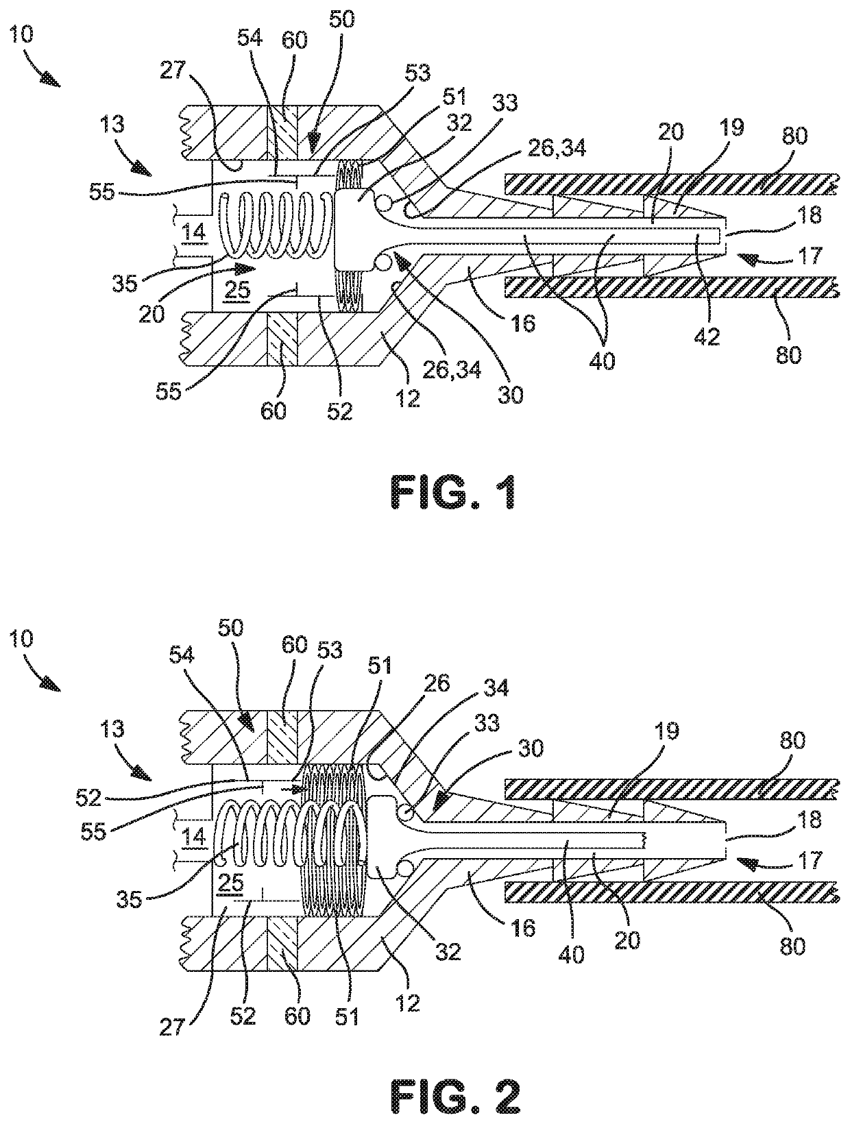
[0015]The presently disclosed gas flow arrestor device includes a conventional firebreak that is configured to shut or stops the flow of gas in the presence of a fire or flame proximate the firebreak and a visual flow indicator that is actuated by the flow of gas through the gas flow arrestor device. The visual flow indicator allows a user or patient to visually confirm from a distance whether or not gas is flowing to the patient or breathing apparatus. Optionally, the gas flow arrestor device may also include a coupling detection mechanism that prevents flow of the gas through the device unless the flexible tubing or hose is coupled to the outlet of the flow arrestor device. Details of select embodiments of the present gas flow arrestor device are provided in the paragraphs that follow.

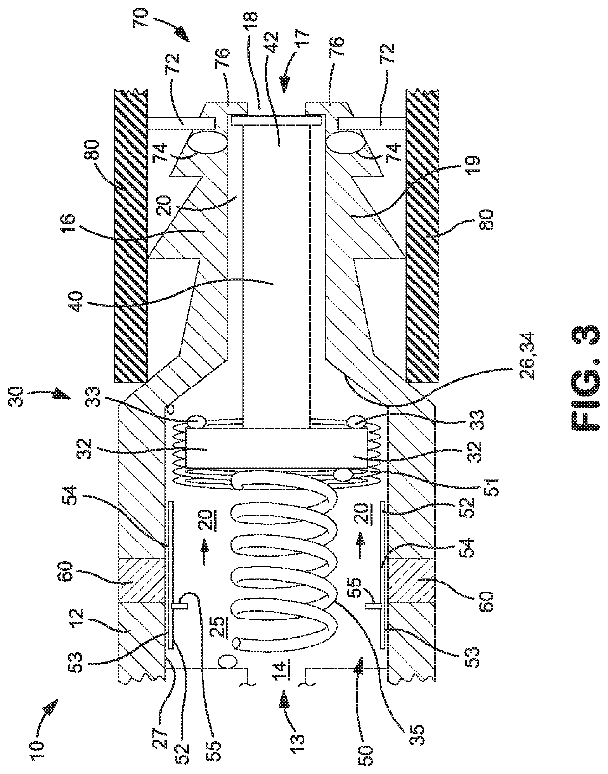
[0016]Turning now to the drawings, there is shown a partial cross section view of an embodiment of the gas flow arrestor device 10 configured to be coupled at one end to a concentrator, a VIPR device...


PUM


Abstract

A gas flow arrestor is provided that is configured to be coupled at one end to an oxygen concentrator, a VIPR type device associated with a compressed gas cylinder, or other gas delivery component such as a regulator or flowmeter and at the opposing end to a length of flexible tubing or hose that delivers the medical gas to the patient or patient breathing apparatus, such as a nasal cannula or breathing mask. The gas flow arrestor device includes a firebreak together with a visual flow indicator that is actuated by the flow of gas through the gas flow arrestor device. The visual flow indicator allows a user or patient to visually confirm from a distance whether or not gas is flowing to the patient or breathing apparatus.

Description

CROSS REFERENCE TO RELATED APPLICATIONS[0001]The present application claims priority from U.S. Provisional Patent Application Ser. No. 62 / 671,043 filed on May 14, 2018, the disclosure of which is incorporated by reference herein.TECHNICAL FIELD[0002]The present invention relates to gas flow arrestor devices for medical gas applications, and more particularly to a gas flow arrestor device configured to be coupled at one end to an oxygen concentrator, a VIPR device associated with a compressed gas cylinder or other medical gas delivery component and at the opposing end to a length of flexible tubing or hose that delivers the medical gas to the patient or patient breathing apparatus, such as a nasal cannula or breathing mask.BACKGROUND[0003]Medical gases such as medical oxygen used for respiratory assistance in a patient is typically provided from an oxygen concentrator or a compressed gas cylinder having a valve integrated pressure regulator (VIPR). The VIPR device coupled to the comp...

Claims


Application Information

Patent Timeline
Patent Type & Authority Applications(United States)
IPC IPC(8): A61M16/20F17C13/04A61M16/06A61M16/00
CPCA61M16/208F17C2270/025A61M16/06A61M16/0003A61M2202/0208F17C2205/0323F17C13/04A61M16/0672A61M2016/003A61M16/0087A61M16/0816A61M16/1005A61M16/20F16K17/383F16K37/0058A61M2205/584A61M2205/8281
Inventor GAMARD, STEPHAN CHRISTOPHE FERNANDDAVIES, CHRISTOPHER HUGH
Owner PRAXAIR TECH INC
Why Eureka
Try Eureka