
Modular vault assembly

a module and vault technology, applied in the direction of building locks, constructions, construction fastening devices, etc., can solve the problems of heavy safes, cumbersome transportation and installation, and difficult to transport and install, so as to facilitate the entrance and withdrawal of the mobile cart, and facilitate storag

Inactive Publication Date: 2019-11-28
MDC IND DE CONTEINERES INTELIGENTES LTDA
View PDF0 Cites 8 Cited by
  • Summary
  • Abstract
  • Description
  • Claims
  • Application Information

AI Technical Summary

Benefits of technology

The present invention is a modular vault assembly that can store various items including larger ones such as computers, tablets, and laboratory equipment. It also includes a cart vault for storing a mobile cart. The interior supporting floor of the cart vault is positioned in a level orientation with an adjacent exterior supporting surface, which makes it easier to access the items stored in the vault. The vault has sensor assemblies to indicate the status of the doors, which can be visually displayed and have audible indicators or alarms. The technical effect of the invention is that it provides a secure and efficient solution for storing and accessing various items while also being convenient for users.

Problems solved by technology

However, protective structures utilizing this type of construction are heavy, cumbersome and are sometimes integrated into the construction of a building in which they are located.
Big safes are extremely heavy and therefore hard to transport and install.
The logistics associated with the manufacturer, handling, transporting, etc. of safes or like protective structures becomes burdensome.
In many cases these construction projects are expensive, lengthy and require special personnel and conditions under which installation and / or construction may be accomplished.
It is commonly recognized that such joints, seams and like interfacing portions of a vault are frequently the most vulnerable or weakest area of the vault.
As a result, unauthorized entry is frequently attempted by attacking such areas using a variety of different penetrating tools, machinery, etc.

Method used


Image

  • Modular vault assembly
  • Modular vault assembly
  • Modular vault assembly

Examples


Embodiment Construction

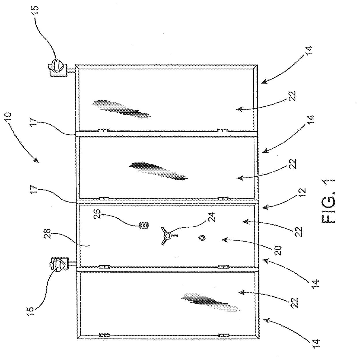
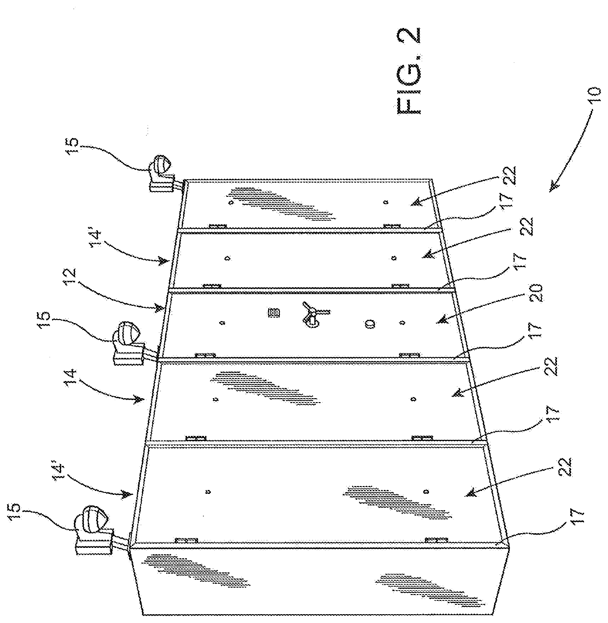
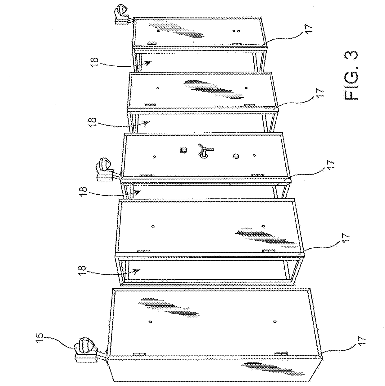
[0035]As represented in the accompanying drawings, the present invention is directed to a modular vault assembly generally indicated as 10 in at least FIGS. 1-3. The modular vault assembly 10 comprises a plurality of vault modules which may vary in number by adding, through interconnection to one another, different numbers of the vault modules. By way of example, and with primary reference to FIGS. 1 and 2 the plurality of vault modules include at least a primary vault 12 and one or more secondary vaults, each indicated as 14. As also represented in FIG. 3, interconnection of the plurality of vault modules, including the primary vault 12 and the one or more secondary vaults 14 is in a continuously successive array, wherein the plurality of vault modules are arranged in immediately adjacent and or contiguous relation to one another.

[0036]A comparison of the modular vault assemblies 10 as represented in FIGS. 1 and 2 indicates that the primary vault module 12 may be accompanied by dif...


PUM


Abstract

A modular vault assembly including a plurality of vault modules variable in number and including a primary vault and one or more secondary vaults. The secondary vaults are interconnected in successively adjacent relation and a leading secondary vault is connected adjacent to the primary vault. The primary vault and each of the secondary vaults respectively include a master door and a slave door having a locking mechanism disposable in a locked and unlocked orientation. The locking mechanism of the leading secondary vault is manually positioned in the unlocked orientation from an interior of said primary vault and each of said locking mechanisms of a remainder of the secondary vaults is manually positioned, successively, in the unlocked orientation from an interior of a preceding, next adjacent one of the plurality of secondary vaults. Each master and slave door includes a sensor assembly indicating the locked orientation of a corresponding locking mechanism.

Description

CLAIM OF PRIORITY[0001]The present application is a Continuation In Part application of U.S. patent application Ser. No. 15 / 602,507 filed on May 23, 2017, which is set to mature to into U.S. Pat. No. 10,316,573 on Jun. 11, 2019, which is based on and a claim of priority is made under 35 U.S.C. Section 119(e) to a provisional of U.S. patent application Ser. No. 62 / 341,915 filed on May 26, 2016, and which is incorporated herein by reference.BACKGROUND OF THE INVENTIONField of the Invention[0002]The present invention relates to safes, vaults and armored cabinets, and, in particular, to a modular vault assembly, which have several vault modules including interior storage compartments and / or enclosures which are connected to one another in a successively adjacent array. Specifically, the present invention relates to the overall structure, components and methods which enable the simplification of logistics and installation, and prevent or significantly restrict a break-in or other unautho...

Claims


Application Information

Patent Timeline
IPC IPC(8): E05G1/08E05G1/10E05G1/026E05G1/04E05B65/00E05B39/00
CPCE05B39/00E05B65/0075E05C9/06E05G1/026E05G1/04E05G1/08E05G1/10E05C9/04
Inventor GREEN, MARCYAELI, YORAM
Owner MDC IND DE CONTEINERES INTELIGENTES LTDA
Learn More