Shaping apparatus and shaping method

Inactive Publication Date: 2019-12-12
MIMAKI ENG
View PDF0 Cites 1 Cited by
  • Summary
  • Abstract
  • Description
  • Claims
  • Application Information

AI Technical Summary

Benefits of technology

The present patent aims to solve the problem of inefficient and appropriate removal of a support layer during shaping of a product. The disclosed shaping apparatus and method allow for efficient and effective removal of the support layer.

Problems solved by technology

However, the removal of the support layer may take, for example, a long time of several hours to several days.
Moreover, in this case, the replacement of the removal tank may not necessarily be performed for each one of the shaped object, but may be performed when the removal tank accommodates a predetermined number of shaped objects.

Method used


Image

  • Shaping apparatus and shaping method
  • Shaping apparatus and shaping method
  • Shaping apparatus and shaping method

Examples


Embodiment Construction

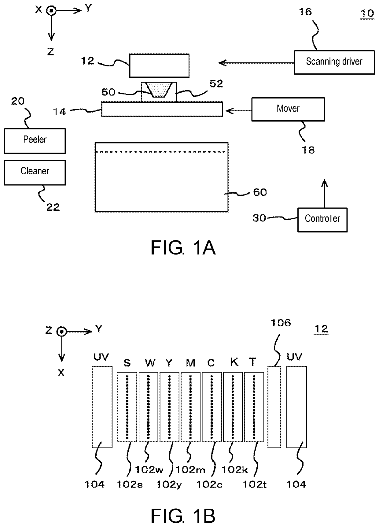
[0032]Hereinafter, an embodiment according to the present disclosure will be described with reference to the drawings. FIGS. 1A and 1B shows one example of a shaping apparatus 10 according to one embodiment of the present disclosure. FIG. 1A shows one example of a configuration of a main part of the shaping apparatus 10. FIG. 1B shows an example of the configuration of a head portion 12 in the shaping apparatus 10.

[0033]Other than the points described below, the shaping apparatus 10 may have a configuration same as or similar to a known shaping apparatus. More specifically, other than the points described below, the shaping apparatus 10 may have a configuration same as or similar to, for example, a known shaping apparatus that carries out shaping by ejecting a droplet to become the material of a shaped object 50 using an inkjet head. Furthermore, other than the illustrated configuration, the shaping apparatus 10 may also include, for example, various types of configurations necessar...


PUM

PropertyMeasurementUnit
Fractionaaaaaaaaaa
Timeaaaaaaaaaa
Widthaaaaaaaaaa

Abstract

A shaping apparatus that shapes a three-dimensional shaped object includes inkjet heads which are shaping material heads that eject materials of the shaped object; an inkjet head which is a support material head that ejects a material of a support layer that supports at least one part of the shaped object being shaped; and a mover that moves the shaped object together with the support layer toward a removal tank, which is a container for accommodating the shaped object at the time of removing the support layer.

Description

CROSS REFERENCE TO RELATED APPLICATIONS[0001]This application claims the priority benefit of Japanese Patent Application No. 2018-111665, filed on Jun. 12, 2018. The entirety of the above-mentioned patent application is hereby incorporated by reference herein and made a part of this specification.TECHNICAL FIELD[0002]The present disclosure relates to a shaping apparatus and a shaping method.DESCRIPTION OF THE BACKGROUND ART[0003]Conventionally, a shaping apparatus (3D printer) for shaping a shaped object using an inkjet head is known (see, e.g., Patent Literature 1). In such a shaping apparatus, for example, the shaped object is shaped through the layered shaping method by overlapping a plurality of layers of ink formed by the inkjet head.[0004]Patent Literature 1: Japanese Unexamined Patent Publication No. 2015-071282SUMMARY[0005]When shaping a shaped object in the shaping apparatus, a support layer needs to be formed at the periphery and the like of the shaped object depending on ...

Claims


Application Information

Patent Timeline
IPC IPC(8): B29C64/379B29C64/40B29C64/112
CPCB29C64/112B29C64/379B29C64/40B33Y30/00B33Y10/00B29C64/124B29C64/20B29C64/236B29C64/35B29C64/245B29C64/364B08B2230/01
Inventor FURUSE, MASAYUKIIMAI, KENTAMATSUSHIMA, TAKUYAOKAWA, MASAKATSU
Owner MIMAKI ENG
Why Eureka
Try Eureka