Container with Alignment Correcting End for Misaligned Placement With a Displacing Robotic Element

Active Publication Date: 2019-12-26
INVIA ROBOTICS INC
View PDF0 Cites 0 Cited by
  • Summary
  • Abstract
  • Description
  • Claims
  • Application Information

AI Technical Summary

Benefits of technology

The patent is about a container with an alignment correcting end and a displacing robotic element for correcting misaligned placement of the container. The alignment correcting end redirects the container into a slot upon misaligned contact with an edge, wall, or other barrier of the slot. The displacing robotic element provides displacement of the robotic actuators that engage and place the container into the slot in response to the alignment correcting end of the container contacting the slot edge, wall, or other barrier. The technical effect of this invention is to enable accurate placement of containers in slots without the need for precise human vision or dexterity, and to compensate for any shifting or movement of the container due to displacement caused by the alignment correcting end.

Problems solved by technology

This seemingly trivial task is difficult for autonomous machines or robots.
The sensors in combination with the provided programming may provide robotic vision that is less accurate than the human eye and slower in deciphering the world before the cameras and sensors.
The robotic eye-hand coordination is also complicated by the fact that the various actuators that the robots use to engage and move containers or items may not have the same dexterity as the human arm, hand, and fingers.
Minute adjustments that are relatively quick and easy for a human to perform, may be more difficult for robots to perform.
In other words, the actuators may have more limited range of motion, may be slower to move, and may be less accurate in their movements than the human arm, hand, and fingers.

Method used


Image

  • Container with Alignment Correcting End for Misaligned Placement With a Displacing Robotic Element
  • Container with Alignment Correcting End for Misaligned Placement With a Displacing Robotic Element
  • Container with Alignment Correcting End for Misaligned Placement With a Displacing Robotic Element

Examples


Embodiment Construction

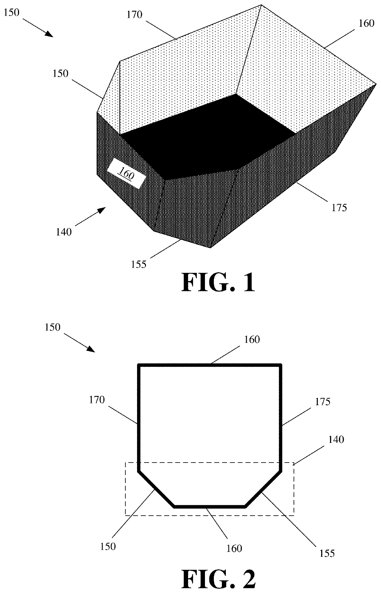
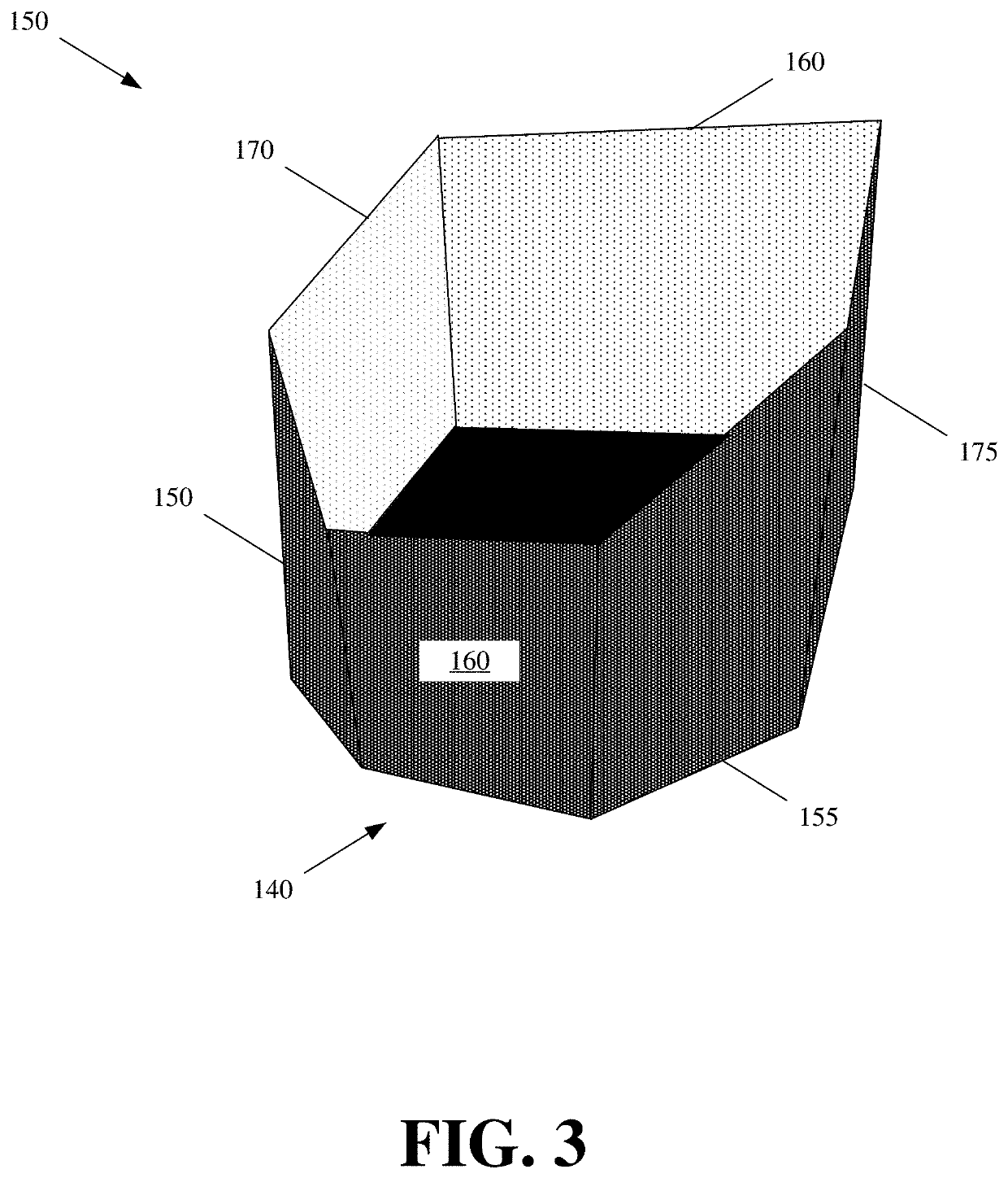
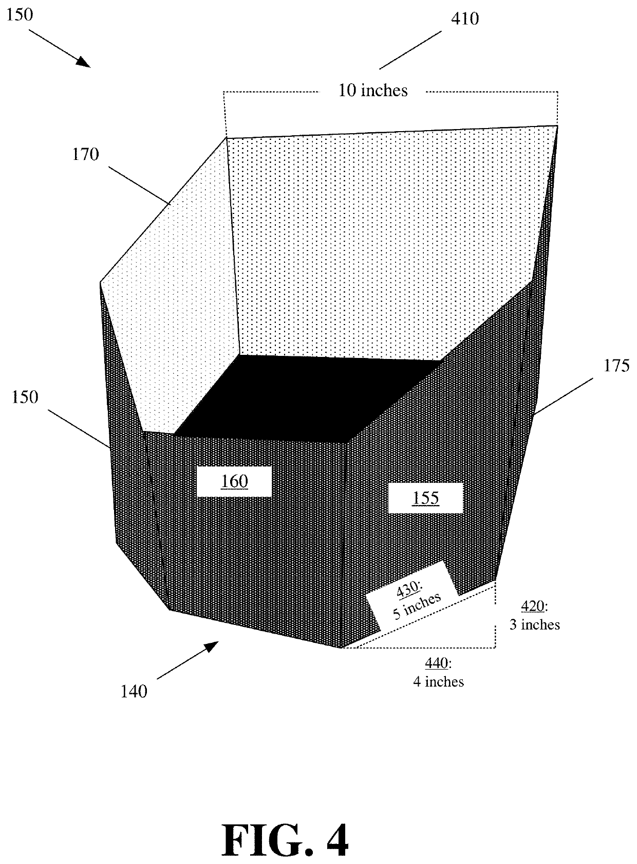
[0021]The disclosure is for a container with an alignment correcting end, and a displacing robotic element for performing misaligned or off-axis placement of the container with the alignment correcting end. The alignment correcting end redirects the container into a slot upon misaligned contact with an edge, wall, or other barrier of the slot. The displacing robotic element provides displacement of the one or more robotic actuators that are used to engage and place the container into the slot in response to the alignment correcting end of the container contacting the slot edge, wall, or other barrier. More specifically, the displacing robotic element corrects alignment of the one or more robotic actuators engaging the container to compensate for any shifting or movement to the container due to displacement caused by the alignment correcting end of the container correcting for misaligned insertion of the container into a slot.

[0022]The slot can be an opening on a rack, shelf, tray, t...


PUM


Abstract

A container with an alignment correcting end is provided. The alignment correcting end has angled side walls that extend from parallel flat square or rectangular sides of the container. Each angled side wall extends at an angle between 5 and 70 from one of the parallel walls towards the center of the container. Nubs may be disposed about an exterior of the angled side walls. Also, a passive displacing robotic element for performing misaligned or off-axis placement of the container with the alignment correcting end is provided. The passive displacing robotic element provides displacement of the one or more robotic actuators that are used to engage and place the container into the slot in response to the alignment correcting end of the container contacting the slot edge, wall, or other barrier.

Description

BACKGROUND INFORMATION[0001]Item or container placement in slots, even tight slots with dimensions close to dimensions of a container, is a relatively easy task for a human. Slots may be openings with two or more barriers or edges about a rack, shelf, or other storage module. The barriers or walls restrict placement of an item or container into the corresponding slot. Human placement of a container into a slot simply involves the human aligning the edges of the container with the barriers or edges of the slot before inserting the container into that slot.[0002]This seemingly trivial task is difficult for autonomous machines or robots. Robots have to be programmed with the necessary “eye-hand” coordination, whereby one or more cameras and other sensors serve as the robot's eyes, and various actuators (e.g., articulating robotic arms, mechanical claws, suction elements, etc.) serve as the robot's hand for manipulating and placing a container or other object in one or more dimensions.[...

Claims


Application Information

Patent Timeline
IPC IPC(8): B65D1/22B65G1/04
CPCB65G1/04B65G2201/0235B65D1/22B65D1/40B66F9/195B66F9/18B66F9/063B65G1/0435
Inventor CARSON, CORWINTRAVERSO, JOSEPHVOORHIES, RANDOLPH CHARLESELAZARY, LIORPARKS, II, DANIEL FRANK
Owner INVIA ROBOTICS INC
Why Eureka
Try Eureka