Eureka AIR delivers breakthrough ideas for toughest innovation challenges, trusted by R&D personnel around the world.

Door closure noise dampening system with auto deadbolt door lock

Inactive Publication Date: 2020-01-16
QUIET SOURCE TECH LLC
View PDF0 Cites 4 Cited by
  • Summary
  • Abstract
  • Description
  • Claims
  • Application Information

AI Technical Summary

Benefits of technology

The noise dampening closure for doors is designed to reduce the amount of noise and vibration when a door is opened and closed. It includes two tabs that are designed to engage with a rotatable element on a pivotable arm. When the door is moved from an open position to a closed position, the tabs cause the arm to move and secure the door. The arm is also designed to move when the door is opened, allowing the tabs to disengage and the arm to move back into its original position. The technical effect of this design is to provide a quieter and more stable closing action for doors, improving the overall experience for users.

Problems solved by technology

Accordingly, the adjustment is typically set to overcompensate for those situations when there is no force keeping the door from closing and thus, because of the force exerted by the automatic door closure mechanism on the door causing it to slam against the metal frame; and further, because of the sudden release of the door latch into the metal latch striker plate in the metal frame, a significant amount of noise is generated when such doors close and latch.
Such noise may not be a factor in commercial or industrial settings however, such a door closure at 2 AM in a hotel setting can disrupt the sleep of individuals in one or more adjoining rooms, much to the displeasure of those individuals.
An additional source of noise in such commercial doors is the deployment of an automatic deadbolt that automatically deploys when the door is proximate the metal doorframe and striker plate.
The second factor contributing to noise with the automatic deadbolt is the material with which the deadbolt first makes contact after release.
For example, the deadbolt (metal) striking the bare metal striker plate makes a loud, sharp noise.

Method used


Image

  • Door closure noise dampening system with auto deadbolt door lock
  • Door closure noise dampening system with auto deadbolt door lock
  • Door closure noise dampening system with auto deadbolt door lock

Examples


Embodiment Construction

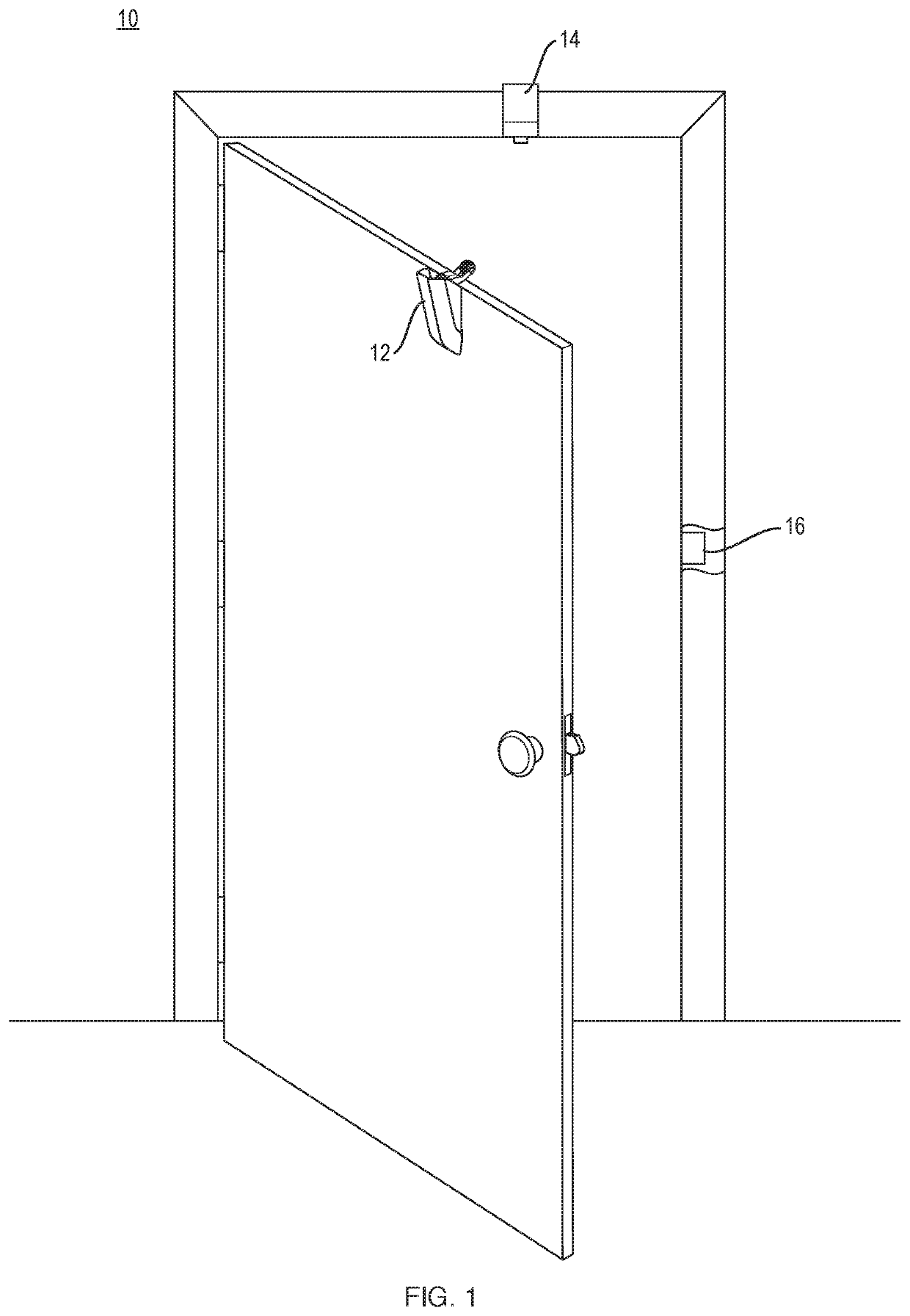
[0031]The present invention features a door closure noise dampening system configured for being installed on a door and illustrated generally at 10, FIG. 1. The system 10 includes, in the preferred embodiment, 3 portions including: a door mounted noise dampening closure portion 12; a door frame mounted noise dampening receiver portion 14 and a door frame mounted striker plate portion 16. The doorframe mounted striker plate portion 16 may be utilized stand-alone, without the door mounted noise dampening closure portion 12 and / or the doorframe mounted noise dampening receiver portion 14, although all 3 system portions work together to provide all of the essential features required in an attempt to ensure quiet door closure and automatic latching.

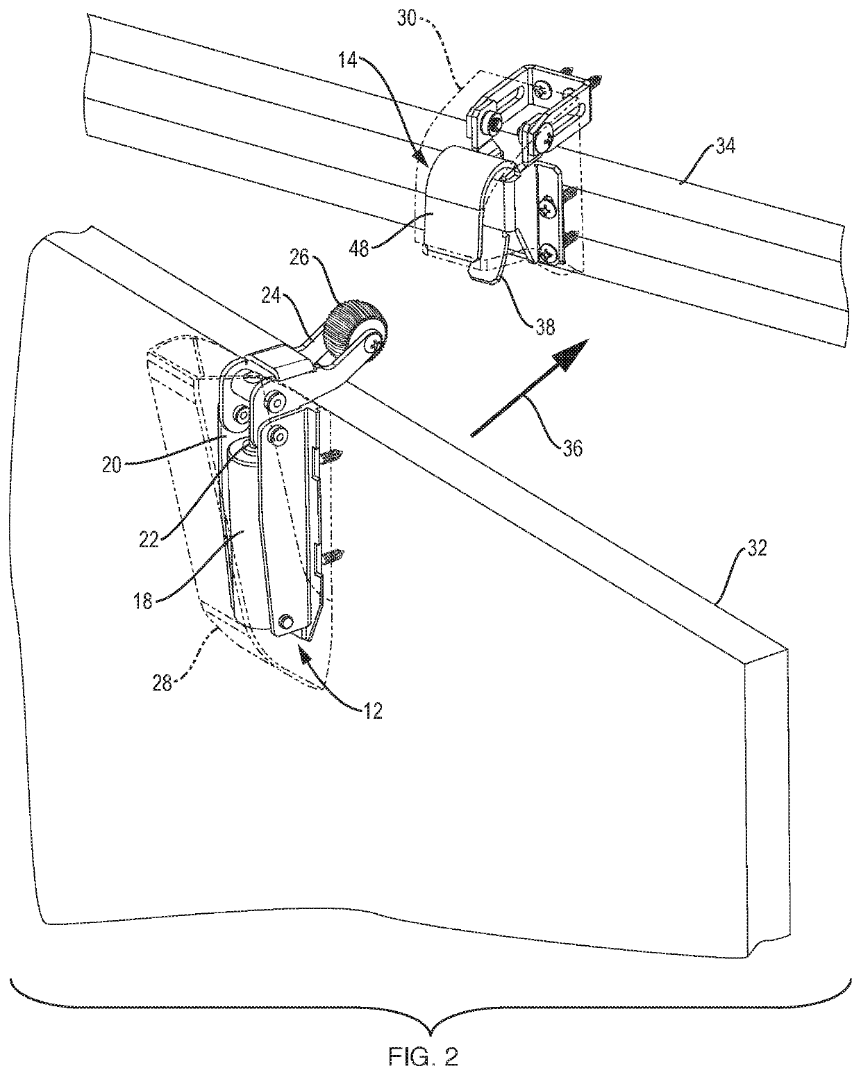
[0032]A first portion of the door closure noise dampening system 10 according to the teachings of the present invention is the door mounted noise dampening portion 12, FIG. 2 and FIGS. 4A and 4B. The door mounted noise dampening portion 12 inc...


PUM


Abstract

A system for ensuring that a door automatically closes and latches while simultaneously ensuring that it does so in a manner which either eliminates or significantly minimizes the amount of noise such closure causes while making sure that the door does in fact fully close and latch. A door mounted portion includes a piston attached to a pivotable arm having a wheel on the end of the arm configured to engage with a doorframe mounted portion to slow the travel of the door into the doorframe while pulling the door into the doorframe to ensure secure closure of the door. A doorframe mounted striker plate portion is configured with at least one spring-loaded striker damper or flap against which a door latch and / or automatically deploying deadbolt lock engages, to slow the engagement of the door latch or deadbolt with striker region in the frame to minimize noise.

Description

CROSS-REFERENCE TO RELATED APPLICATIONS[0001]This application claims priority from U.S. Provisional Patent Application No. 62 / 517,547 filed on Jun. 9, 2017 and titled “DOOR CLOSURE NOISE DAMPENING SYSTEM” and U.S. Provisional Patent Application No. 62 / 537,518 entitled “DOOR CLOSURE NOISE DAMPENING SYSTEM WITH AUTO DEADBOLT DOOR LOCK” filed on Jul. 27, 2017, both of which are incorporated fully herein by reference.TECHNICAL FIELD[0002]The present invention relates to automatically closing commercial doors such as found in hotel rooms and office buildings and more particularly, relates to a three-piece door closing and dampening system designed to eliminate and / or significantly minimize the amount of noise caused by a door closed by a manually or automatically driven door closer and to an auto deadbolt receiving striker plate.BACKGROUND INFORMATION[0003]There are many instances where automatic door closing systems are utilized on and in connection with commercial doors to ensure that ...

Claims


Application Information

Patent Timeline
IPC IPC(8): E05B17/00E05B15/02E05B9/02
CPCE05B17/0045E05Y2900/132E05Y2800/422E05B15/022E05B9/02E05F5/027E05Y2201/626E05Y2201/688
Inventor SCHAPPLER, JOSEPH J.MCKOWEN, KEVINSTRATTON, ALAN K.CARPENTER, DAVID
Owner QUIET SOURCE TECH LLC
Why Eureka
Eureka Blog
Learn More