Friction liner and traction sheave

a friction liner and traction sheath technology, applied in the field of friction liner and traction sheath, can solve the problems of adverse effects on ride quality, difficulty in installation, and inability to work with liners and the method of attaching the liners,

Active Publication Date: 2020-02-20
OTIS ELEVATOR CO
View PDF32 Cites 5 Cited by
  • Summary
  • Abstract
  • Description
  • Claims
  • Application Information

AI Technical Summary

Problems solved by technology

These liners and method of attaching the liners may not work with liner materials having low elasticity.
Using chain connectors may result in adverse effects on ride quality, may require special tooling, and may be difficult to install.
Using wedge shaped liner that frictionally interlocked may be time consuming to install and remove.

Method used


Image

  • Friction liner and traction sheave
  • Friction liner and traction sheave
  • Friction liner and traction sheave

Examples


Embodiment Construction

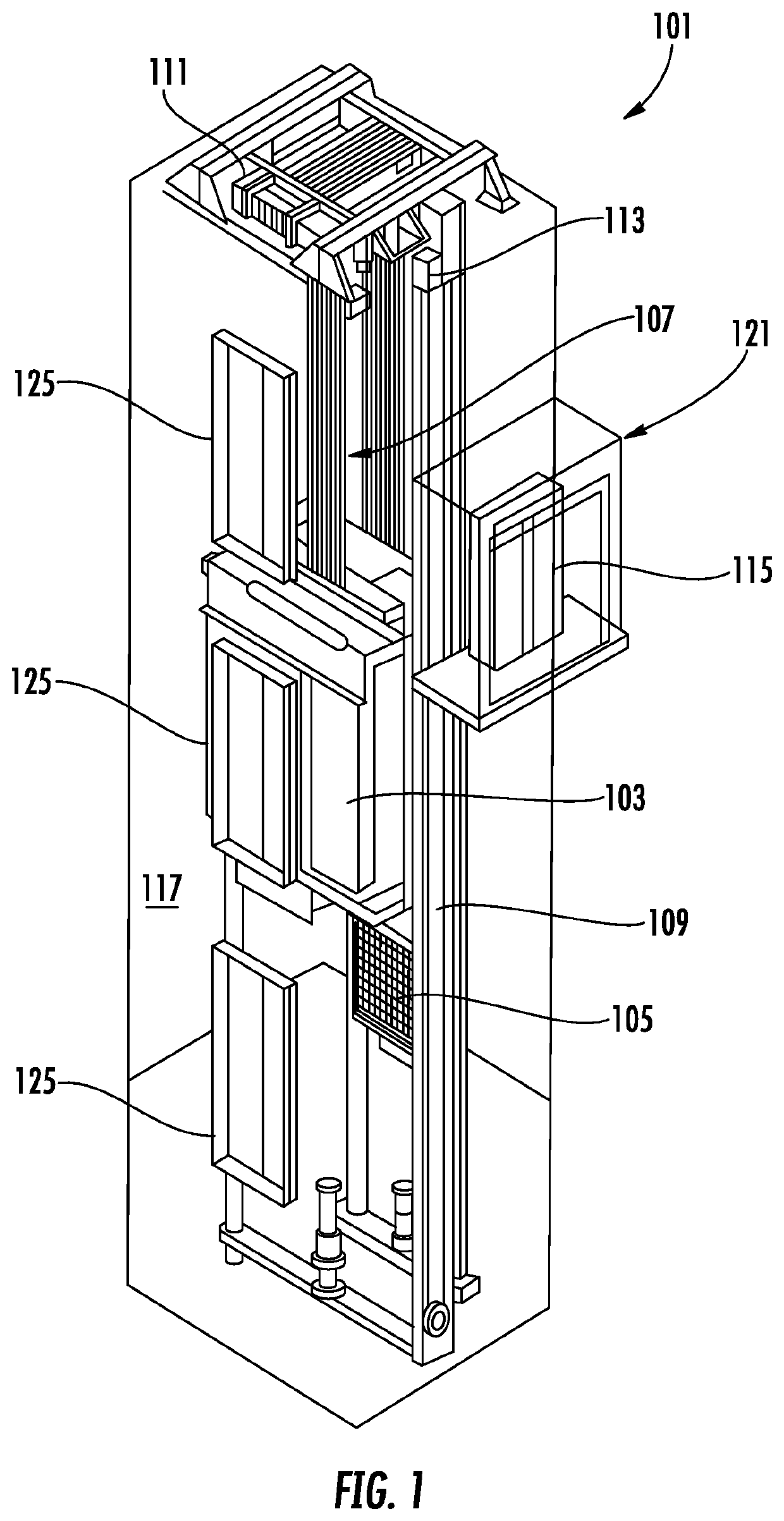
[0030]FIG. 1 is a perspective view of an elevator system 101 including an elevator car 103, a counterweight 105, a tension member 107, a guide rail 109, a machine 111, a position reference system 113, and a controller 115. The elevator car 103 and counterweight 105 are connected to each other by the tension member 107. The tension member 107 may include or be configured as, for example, ropes, steel cables, and / or coated-steel belts. The counterweight 105 is configured to balance a load of the elevator car 103 and is configured to facilitate movement of the elevator car 103 concurrently and in an opposite direction with respect to the counterweight 105 within an elevator shaft 117 and along the guide rail 109.

[0031]The tension member 107 engages the machine 111, which is part of an overhead structure of the elevator system 101. The machine 111 is configured to control movement between the elevator car 103 and the counterweight 105. The position reference system 113 may be mounted on...


PUM


Abstract

Disclosed is a liner for a traction sheave including a top surface and a bottom surface mutually spaced on a height-wise axis (H), a front surface and a back surface mutually spaced on lengthwise axis (L), and a plurality of side surfaces including a first side surface and a second side surface mutually spaced in a widthwise axis (W), wherein in a first cross sectional profile of the plurality of side surfaces forms convergent-divergent profile.

Description

BACKGROUND[0001]The embodiments herein relate to elevator sheaves and more specifically to a friction liner and a traction sheave.[0002]Traction liners may be stretched over a sheave with the ends of a traction liner connected using a chain, or otherwise fastened to the sheave. These liners and method of attaching the liners may not work with liner materials having low elasticity. Using chain connectors may result in adverse effects on ride quality, may require special tooling, and may be difficult to install. Using wedge shaped liner that frictionally interlocked may be time consuming to install and remove.BRIEF SUMMARY[0003]Disclosed is a liner for a traction sheave comprising a top surface and a bottom surface mutually spaced on a height-wise axis (H), a front surface and a back surface mutually spaced on lengthwise axis (L), and a plurality of side surfaces including a first side surface and a second side surface mutually spaced in a widthwise axis (W), wherein in a first cross ...

Claims


Application Information

Patent Timeline
Patent Type & Authority Applications(United States)
IPC IPC(8): B66B15/04
CPCB66B15/04B66B7/02
Inventor HUBBARD, JAMES L.TORLAI, DAVID R.KEYO, PETER
Owner OTIS ELEVATOR CO
Why Eureka
Try Eureka