
Turbomachine with axial force recovery at the fan via pressurized gas feed

a turbomachine and axial force technology, applied in the field of turbomachines, can solve the problems of accelerating bearing wear, weak axial force, and degradation of thrust ball bearings

Active Publication Date: 2020-03-05
SN DETUDE & DE CONSTR DE MOTEURS DAVIATION S N E C M A
View PDF0 Cites 0 Cited by
  • Summary
  • Abstract
  • Description
  • Claims
  • Application Information

AI Technical Summary

Benefits of technology

The invention is a turbomachine with the following features: a gas feed duct with a valve, an enclosure limited by a disc and a bearing support, a gas feed duct piercing the disc, a shaft supported by two bearings, and a second bearing positioned upstream of the first bearing. These features provide protection against degradation over time and can improve performance and reliability of the turbomachine.

Problems solved by technology

However, in some operating phases (e.g. idling, transient phase, engine stop / start, fan autorotation) this axial force may be weak or may be applied in reverse direction.
This may translate as degradation of the thrust ball bearing.
Repeated impacting between the balls and outer and inner races may accelerate wear of the bearing, in particular in the event of repeated alternation in the direction in which the axial force is applied on the bearing.
In addition, if the turbomachine comprises reduction gearing to modify the rotational speed of the fan, the axial forces applied on the fan rotor can also cause load instabilities detrimental to the proper functioning and lifetime of the reduction gearing, e.g. accelerating wear of the chevron-shaped teeth of the gearing.
However, known piston systems are not able to provide sufficient pressurization to obtain thrust on the fan rotor, in particular for engine architecture with reduction gearing.

Method used


Image

  • Turbomachine with axial force recovery at the fan via pressurized gas feed
  • Turbomachine with axial force recovery at the fan via pressurized gas feed
  • Turbomachine with axial force recovery at the fan via pressurized gas feed

Examples


Embodiment Construction

[0036]In the appended Figures, similar elements carry the same number references.

Axial Forces Generated on the Bearings During Engine Operation

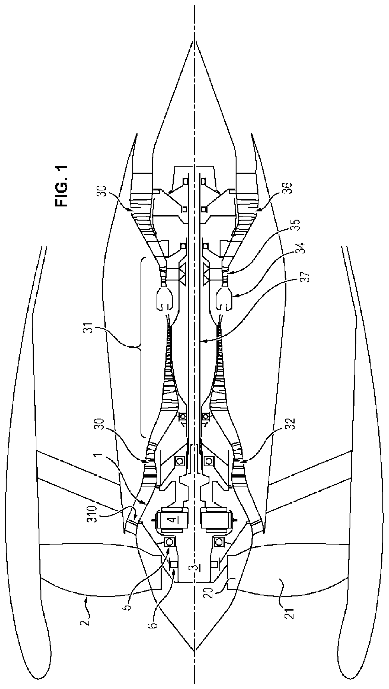
[0037]FIG. 1 is an overall view of a turbomachine with reduction gearing. Said turbomachine, as is conventional, comprises a fan 2 and a primary core which, in the direction of flow, comprises a low-pressure compressor 32 (particularly comprising a first-stage airflow straightener 310), a high-pressure compressor 33, combustion chamber 34, high-pressure turbine 35, low-pressure turbine 36 and exhaust nozzle. The high-pressure compressor 33 and the high-pressure turbine 35 form a high-pressure section 31. The low-pressure compressor 32 and the low-pressure turbine 36 form a low-pressure section 30. The various rotor elements of the turbomachine, as axis of rotation, use axis 37 of the turbomachine, illustrated by a horizontal dotted line in FIG. 1.

[0038]The fan 2 notably comprises a fan disc 20 provided with fan blades 21 on the periphery ther...


PUM


Abstract

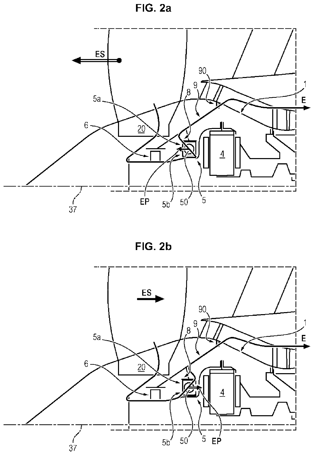
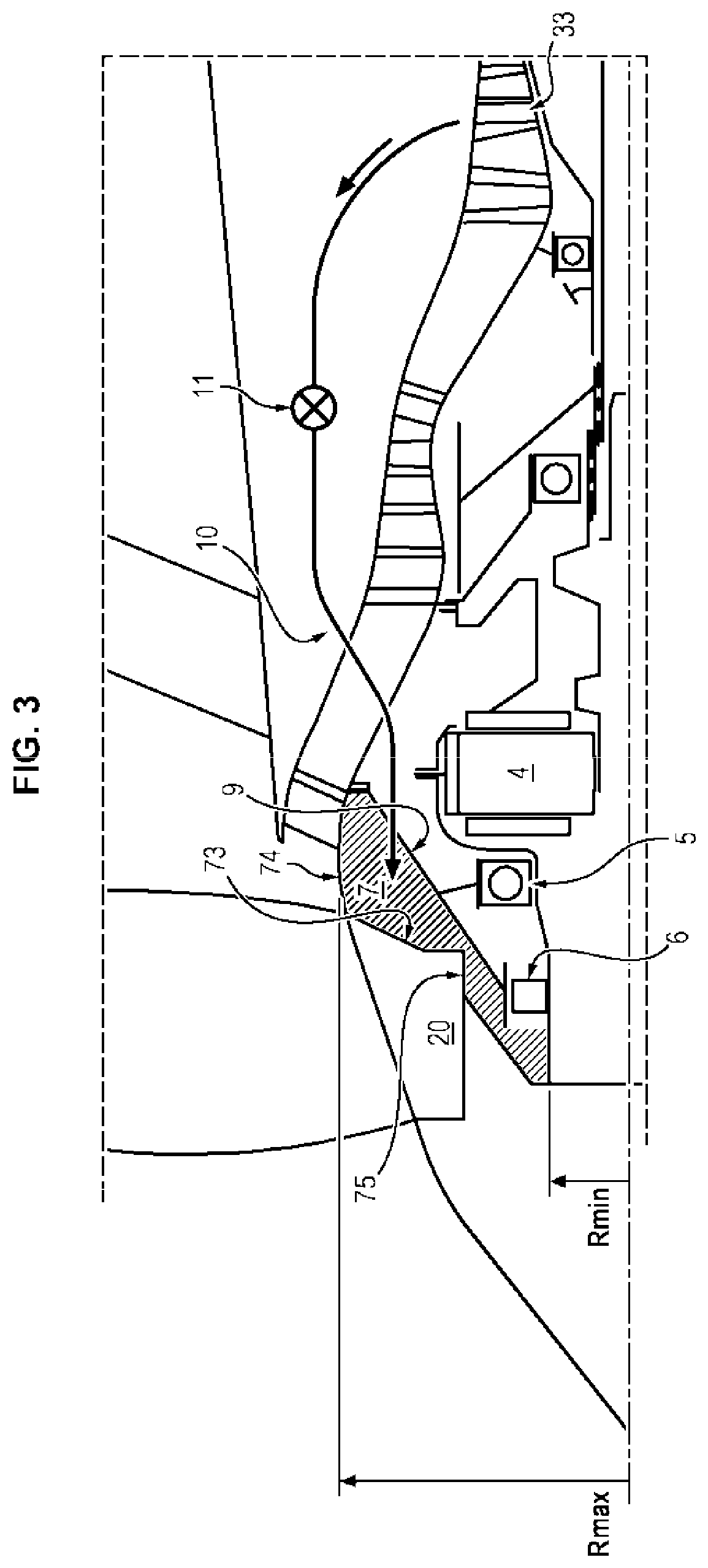
A turbomachine having a fan shaft supported by a first bearing positioned downstream of the fan, the first bearing including an outer ring attached to an annular support secured to the stator. The turbomachine includes at least one gas feed duct leading into an enclosure positioned against the disc, the gas feed duct being adapted to be fed at a second end with pressurized gas taken from an airstream of a high-pressure compressor of the turbomachine, so that the gas applies an axial force towards upstream on the disc during some operating phases of the turbomachine. The turbomachine further includes a ferrule imperviously sealing the enclosure.

Description

GENERAL TECHNICAL FIELD[0001]The present invention relates to turbomachines, and more particularly concerns recovery of axial force at a fan of a turbomachine.PRIOR ART[0002]A two-spool turbomachine, as is conventional, comprises a rotor comprising a fan. The fan speed relative to the low-pressure shaft is modified by reduction gearing e.g. gearing of epicyclic type having a ring gear secured to the fan.[0003]Axial forces are produced by rotation of the fan blades, generated in particular by spinning of the fan blades i.e. twisted deformation of the blades when the engine is in operation. These axial forces are applied to the fan rotor and are taken up by a thrust bearing guiding the movement of the fan, this latter bearing is preferably a ball bearing.[0004]Turbomachines are usually designed so that the axial force at the fan rotor is applied in a preferred direction. In most flight phases the axial force applied by the fan on the thrust bearing is oriented towards the front of the...

Claims


Application Information

Patent Timeline
Patent Type & Authority Applications(United States)
IPC IPC(8): F01D3/00F01D25/16
CPCF05D2260/60F05D2240/52F05D2220/32F01D25/16F01D3/00F05D2240/56F01D3/04F01D25/162F02C7/06F05D2220/36F05D2260/15
Inventor BRAULT, MICHEL GILBERT ROLANDBECOULET, JULIEN FABIEN PATRICKCHASSAGNE, AMELIE ARGIE ANTOINETTEYVON, DIDIER JEAN-LOUIS
Owner SN DETUDE & DE CONSTR DE MOTEURS DAVIATION S N E C M A
Learn More