High operational frequency fixed mesh antenna reflector

Active Publication Date: 2020-03-05
EAGLE TECH LLC
View PDF7 Cites 0 Cited by
  • Summary
  • Abstract
  • Description
  • Claims
  • Application Information

AI Technical Summary

Benefits of technology

The patent is about a new type of reflector and reflector system that can be used for high-frequency operations. The reflector has very precise surface accuracy and geometry. This invention will improve the performance of the reflector and make it easier to use in high-frequency applications.

Problems solved by technology

However, beyond 2 meters, the mass of the reflector, the mass of the boom to position the reflector, and the spacecraft interface structure increases significantly, which may be problematic for satellite reflectors.
In addition, achievable surface accuracy on solid surface reflectors greater than two (2) meters decreases making it difficult to achieve the surface accuracy required for high operational frequencies, e.g., Ka-band and greater.
The surface accuracy is limited by fabrication errors typically associated with tooling and mold errors, distortions associated with elevated temperature cure required for current manufacturing techniques, and thermal elastic distortions of the reflector.
However, like solid surface reflectors, achievable surface accuracy on fixed mesh reflectors greater than two (2) meters decreases making it difficult to achieve the surface accuracy required for high operational frequencies, e.g., Ka-band and greater.
Surface accuracy is limited in fixed mesh reflectors by fabrication errors caused by the mold and tooling, distortions induced into the mesh surface during mesh surface installation, and thermal elastic distortions of the reflector.

Method used


Image

  • High operational frequency fixed mesh antenna reflector
  • High operational frequency fixed mesh antenna reflector
  • High operational frequency fixed mesh antenna reflector

Examples


Embodiment Construction

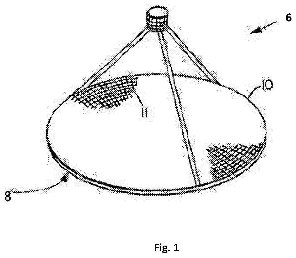
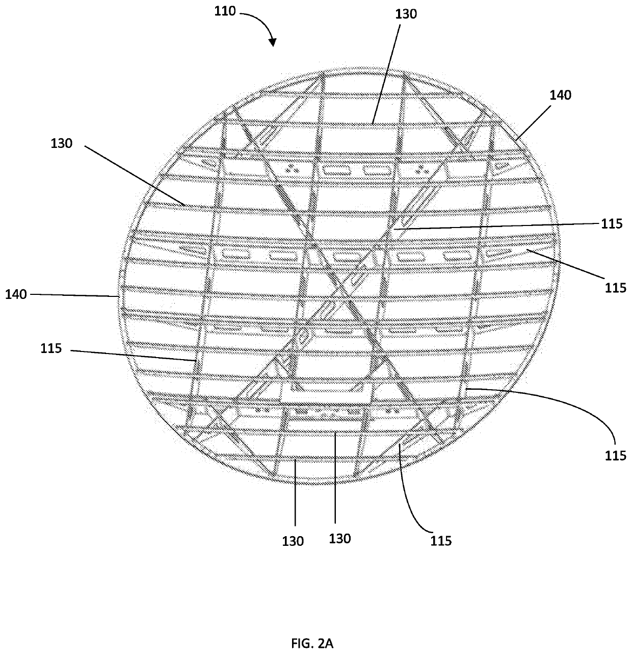
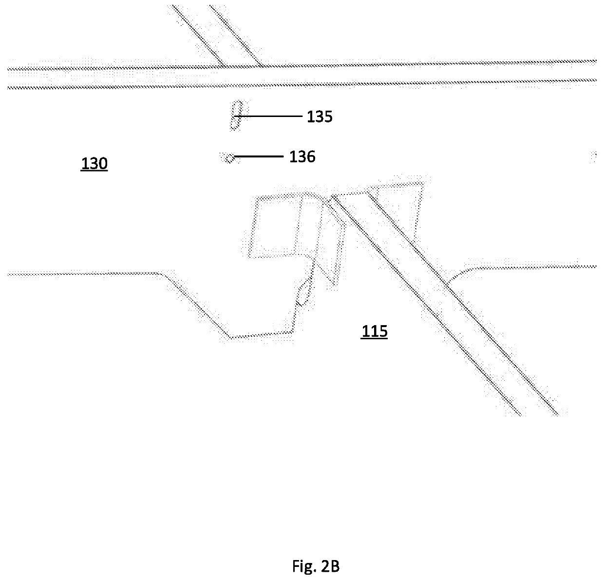
[0037]The following description is made for illustrating the general principles of the invention and is not meant to limit the inventive concepts claimed herein. In the following detailed description, numerous details are set forth in order to provide an understanding of the reflector, the reflector structure, the reflector system, and their method of manufacture and operation, however, it will be understood by those skilled in the art that different and numerous embodiments of the reflector, reflector structure, reflector system, and their method of manufacture and operation may be practiced without those specific details, and the claims and invention should not be limited to the embodiments, subassemblies, features, processes, methods, aspects, or details specifically described and shown herein. Further, particular features described herein can be used in combination with other described features in each of the various possible combinations and permutations.

[0038]Accordingly, it w...


PUM


Abstract

A reflector antenna, preferably a fixed mesh reflector antenna, and a process for manufacturing the reflector antenna, is disclosed that includes forming a support structure, placing a reflector surface on a mold, attaching the support structure to the reflector surface, measuring the geometry of the reflector surface, adjusting the surface geometry of the reflector if appropriate to obtain improved accuracy for the reflector surface, and fixedly connecting the support structure and the reflector surface. In an embodiment, the antenna reflector system includes a mesh reflector surface, a plurality of spline support elements, a plurality of splines connected to the reflector surface, and a plurality of adjustable spline supports attachable to the spline support elements and the splines, wherein the adjustable spline supports are adjustably repositionable with respect to the spline support elements, and also fixedly connectable to the spline support elements.

Description

FIELD OF THE INVENTION[0001]The present invention relates to antennas or reflectors for terrestrial or space applications and in an embodiment relates to a new and improved high operational frequency antenna or reflector that is lightweight and highly reflective.BACKGROUND OF THE INVENTION[0002]The use of large reflectors for satellite communication networks is becoming more widespread as the demand for mobile communications increases. One area where demand is increasing is for antennas or reflectors having a diameter of approximately two (2) meters to approximately five (5) meters for high operational frequency applications (e.g., Ka-Band, V-Band).[0003]Solid surface reflectors may be used for applications up to two (2) meters and in circumstances may be capable of achieving serviceable accuracy required for operational frequencies up to 50 GHz. However, beyond 2 meters, the mass of the reflector, the mass of the boom to position the reflector, and the spacecraft interface structur...

Claims


Application Information

Patent Timeline
IPC IPC(8): H01Q15/16H01Q1/12H01Q15/14
CPCH01Q15/168H01Q15/147H01Q1/12H01Q1/14H01Q15/141H01Q19/13
Inventor SORRELL, RODNEY
Owner EAGLE TECH LLC
Why Eureka
Try Eureka