Method and apparatus for determining the complex impedance of an electrical component

Inactive Publication Date: 2005-01-27
JAMES G BIDDLE
View PDF16 Cites 21 Cited by
  • Summary
  • Abstract
  • Description
  • Claims
  • Application Information

AI Technical Summary

Benefits of technology

[0031] The duration for which the signal is applied is preferably such that it contains an integer number of cycles of each of the discrete frequencies. Preferably, the minimum duration that satisfies this condition is chosen in order to minimise the amount of processing required. The input signal as a whole is then aperiodic as it does not repeat itself.
[0036] Preferably, the number of samples in the sequence is the lowest common multiple of all of the frequencies Fi in Hz multiplied by the lowest factor that R such that all Fi*R are integers. Preferably, the sequence length allows the demodulation to be performed over a whole number of cycles simultaneously for each of the discrete frequencies.
[0037] Preferably, a noise signal is also applied across the terminals of the battery simultaneously with the discrete frequencies. The noise signal can ameliorate problems arising from quantisation which occurs as a result of the input signal being applied as a sequence of samples.
[0053] Preferably, the processing means includes a plurality of circular accumulators. Preferably, the processing means includes a circular accumulator corresponding to each impedance related parameter at each discrete frequency, the length of each accumulator corresponding to the number of samples per cycle at that frequency. The circular accumulators form part of a Homodyne demodulation system designed to operate so as to detect only the desired frequency in order to reduce the number of calculations required to be performed during demodulation.

Problems solved by technology

Batteries used for all three of the above types of application are susceptible to failure and degradation.
These components will degrade during the life of the battery.
Back up power supply batteries are of necessity, large and have low resistance and high capacitance.
Furthermore, back up power supply batteries are often installed in locations of high electrical noise, such as electricity sub-stations.
This combination of factors makes the accurate determination of battery impedance spectra extremely difficult.
However, there are problems with the method disclosed in GB 2175700A.
In practice, the time constant of a typical battery is long, making frequency which gives rise to the maximum reactance value low and the resulting test length unacceptable.
Furthermore, it is difficult to estimate the maximum value of reactance without taking measurements over the range of frequencies around that maximum value.
The Fourier transform of the entire frequency range takes a long time and the process does not allow any information to be determined until the whole process has completed.
Further problems, not addressed by the above, arise from the presence of large AC and DC voltage and current signals in the battery system during the test.
While small signals would normally be applied for the determination of such an equivalent circuit, this approach must be abandoned in the presence of much larger interfering signals.
As a consequence a method which relies on simultaneous measurements at large numbers of frequencies could produce confusing results with poor repeatability.
At such frequencies the time required for even a single measurement might exceed the patience of the operator.
Therefore, if the constraints caused by intermodulation and harmonics were to result in the need for sequential measurements at individual frequencies the test would become impractical.
This would be unacceptably long however to encompass frequencies both above, and especially below, the frequency at which the battery appears the most reactive.

Method used


Image

  • Method and apparatus for determining the complex impedance of an electrical component
  • Method and apparatus for determining the complex impedance of an electrical component
  • Method and apparatus for determining the complex impedance of an electrical component

Examples


Embodiment Construction

[0074] The present invention will be described with reference to the Randles equivalent model for the resistive and reactive components of a battery. However, it should be clear that the method and apparatus of the present invention can be applied to any model of a battery or to other electrical components.

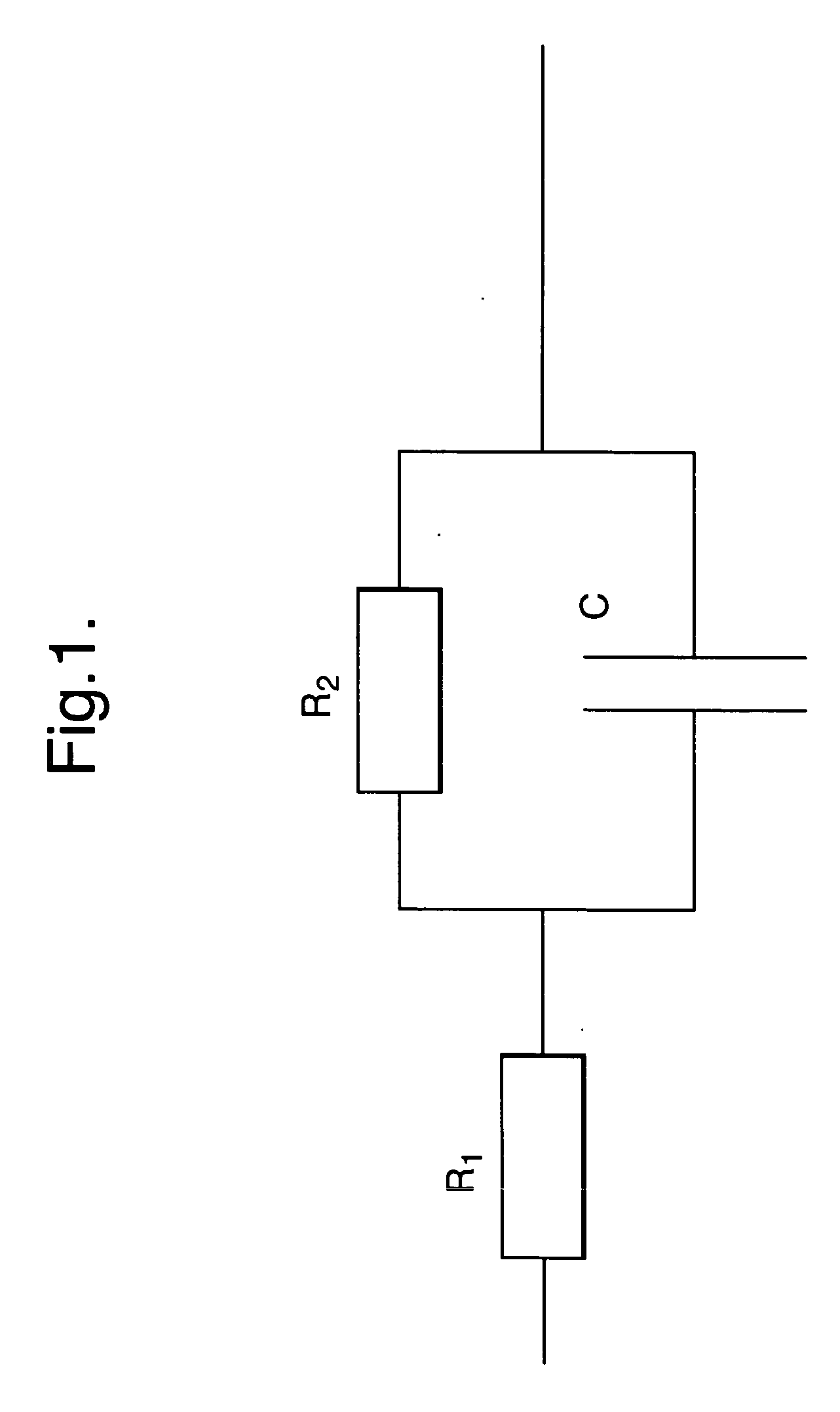
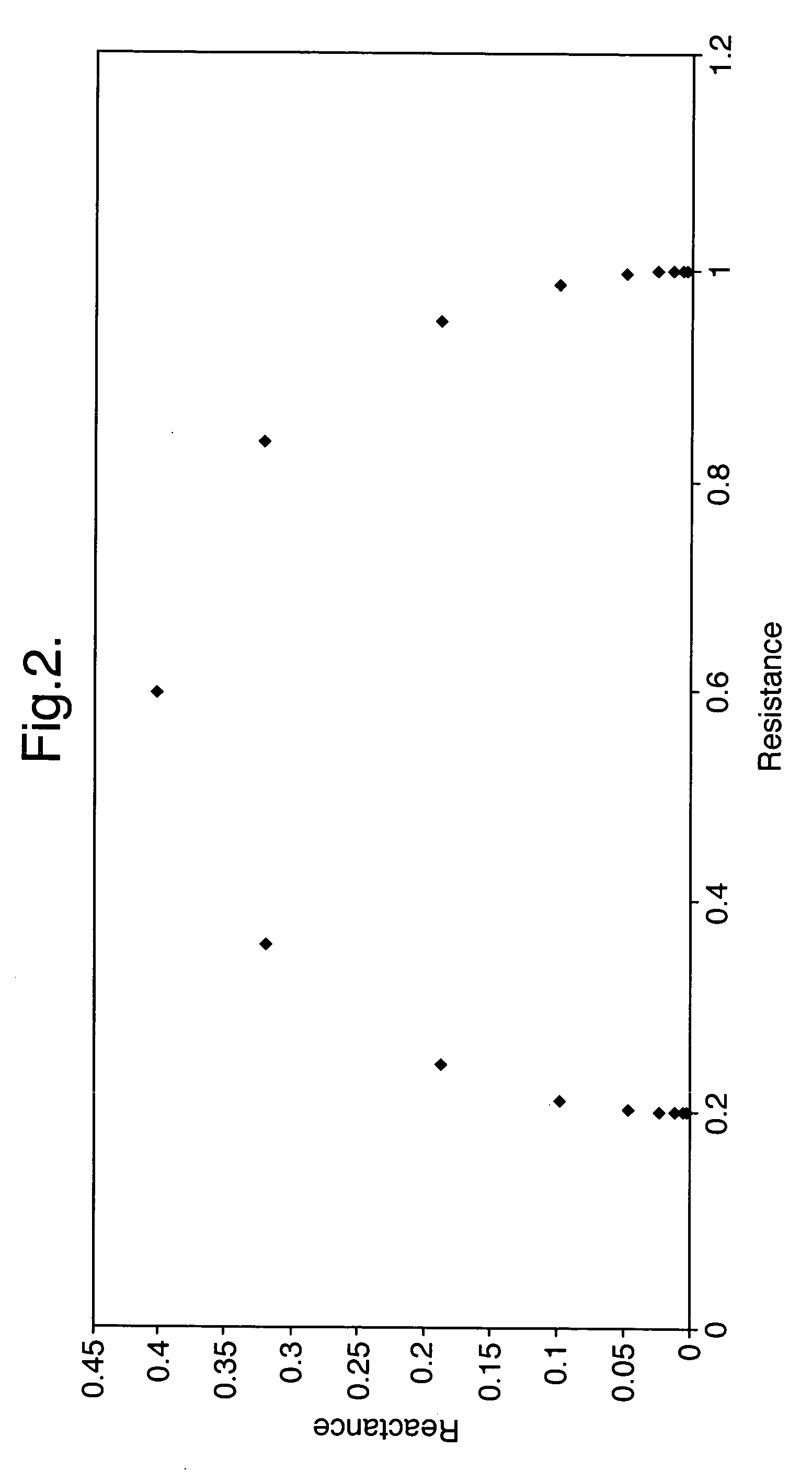
[0075]FIG. 1 shows the Randles equivalent circuit for a battery, comprising a first resistor R1 connected in series with a second resistor R2 and a capacitor C connected in parallel. The complex impedance of this circuit is plotted at a number of frequencies in FIG. 2. Each point plotted in FIG. 2 represents a frequency one octave lower than the next when moving from left to right. The plotted points all lie on a semicircle from which it is possible to determine the point of maximum reactance and hence the values of R1, R2 and C. The point of maximum reactance occurs at a resistance of (R1+R2) / 2 and the maximum reactance equals the radius of the circle i.e. R2 / 2. This allows R1 a...


PUM


Abstract

The invention provides a method and apparatus for determining the complex impedance of an electrical component. The method comprises the steps of applying an input signal to the component comprising a plurality of discrete frequencies simultaneously, and determining the complex impedance of the component at each of the frequencies using a discrete demodulation technique on two complex impedance related parameters at each of the discrete frequencies. This method is particularly useful in electrically noisy environments and can be used to determine the impedance and equivalent circuit parameters for a battery. It can also be applied to battery system interconnects to enable battery system currents to be determined.

Description

FIELD OF THE INVENTION [0001] The present invention relates to a method of analysing the complex impedance spectrum of a circuit or a component in a circuit. In particular the present invention relates to a method of estimating unknown battery degradation using ordinary measurements of the complex impedance spectrum of that battery. BACKGROUND TO THE INVENTION [0002] Batteries are increasingly being used in a wide range of applications. Broadly speaking these can be split into three types: [0003] 1. primary power for use in portable equipment and mobile devices such as fork lift trucks; [0004] 2. start-up power such as for car batteries; and [0005] 3. back-up power for uninterruptible power supplies such as for telephone exchanges. [0006] Batteries used for all three of the above types of application are susceptible to failure and degradation. Degradation normally reduces the capacity of the battery but does not perceptibly affect easily measurable parameters such as output voltage....

Claims


Application Information

Patent Timeline
IPC IPC(8): G01R31/36
CPCG01R31/3662G01R31/389
Inventor MERL, PETERESMET, GEORGELAWRENCE, RICKHEYNEKE, JAN-CHRISTOFFELCLARKE, DAVID
Owner JAMES G BIDDLE
Why Eureka
Try Eureka