Spinal implant device

a bone implant and system technology, applied in the field of system and method of stabilizing bone, can solve problems such as spinal instability and pain, and achieve the effect of quick and/or easy stabilization and/or fixation of bone, enhancing the formation of new bone growth

Active Publication Date: 2020-03-26
SPINAL ELEMENTS INC
View PDF0 Cites 18 Cited by
  • Summary
  • Abstract
  • Description
  • Claims
  • Application Information

AI Technical Summary

Benefits of technology

[0026]Accordingly, a need exists for a spinal implant device to quickly and / or easily stabilize and / or fixate a bone by enhancing the formation of new bone growth to fuse the spinal implant device.

Problems solved by technology

These degenerative changes can produce pain and spinal instability.

Method used


Image

  • Spinal implant device
  • Spinal implant device
  • Spinal implant device

Examples


Embodiment Construction

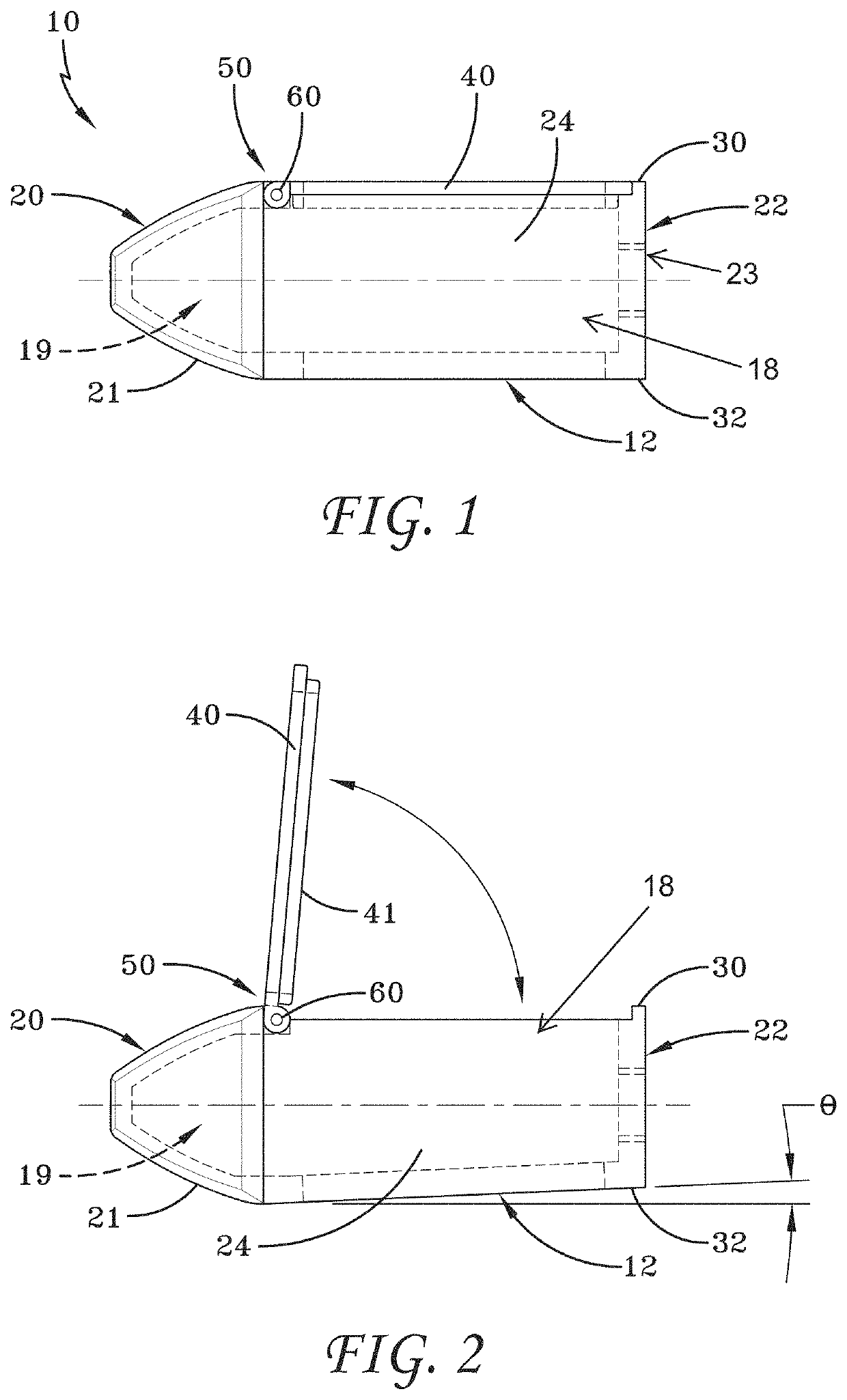
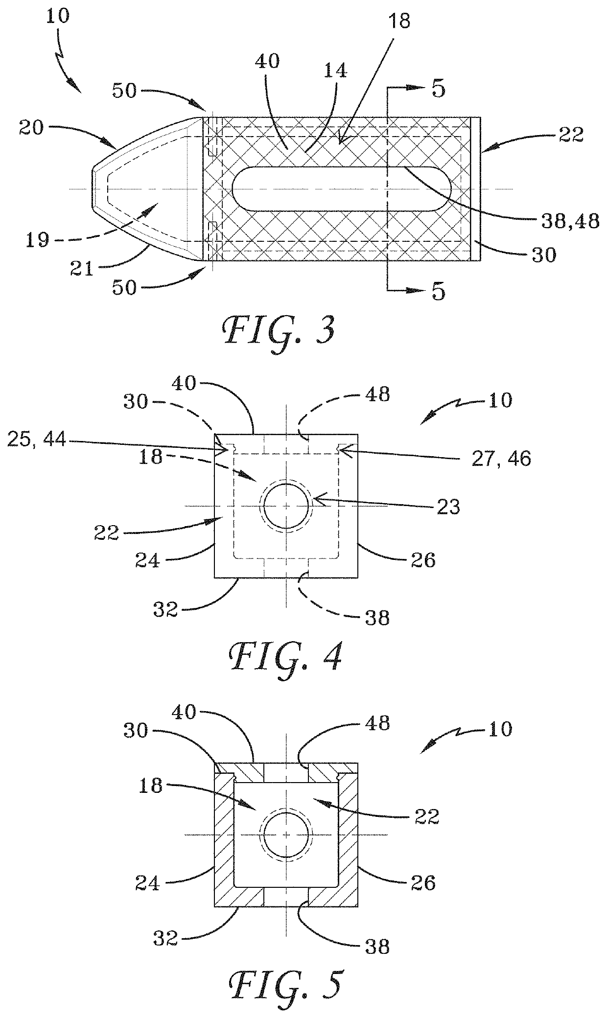
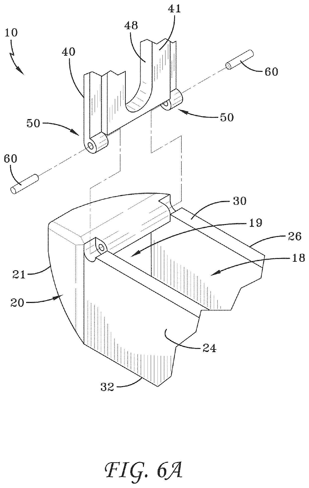
[0212]FIG. 1 illustrates a cross-sectional view of a spinal implant device 10. The spinal implant device 10 can include a body structure 12. The body structure 12 can be placed between adjacent vertebrae, such as a superior vertebra and an inferior vertebra. The orientation of the body structure 12 between the vertebrae can depend on the insertion direction and the methods of use of the spinal implant device 10. The spinal implant device 10 can be placed at any level of the vertebral column, between any adjacent vertebrae. The spinal implant device 10 can be designed to restore or maintain the spacing between adjacent vertebrae. The body structure 12 can include one or more walls which provide strength and stability to the spinal implant device 10.

[0213]The spinal implant device 10 can include a distal end 20. In some methods of use, the distal end 20 is the leading end which is inserted first into the intervertebral space. In some embodiments, the distal end 20 is tapered. The dist...


PUM


Abstract

A spinal implant device is provided comprising a body structure with a central cavity and a movable lid configured to cover the central cavity. The movable lid is configured to be opened to pack a material in the central cavity. The movable lid can be connected to the body structure with a moveable joint. The spinal implant device can include a compressible feature. A method for treating the spine is provided comprising opening a movable lid of a spinal implant device, packing a material in a central cavity of a spinal implant device, closing the movable lid, and inserting the spinal implant device between vertebrae.

Description

CROSS-REFERENCE TO RELATED APPLICATIONS[0001]This application claims priority benefit to U.S. Provisional Patent Application No. 62 / 734,148, filed Sep. 20, 2018, and U.S. Provisional Patent Application No. 62 / 790,866, filed Jan. 10, 2019, the disclosures of each are incorporated by reference herein in their entireties.BACKGROUNDField[0002]Some embodiments described herein relate generally to systems and methods for stabilizing bone, for example, stabilizing vertebrae by fusing adjacent vertebrae. Some embodiments relate to spinal implant devices, for example spinal implant devices with a structure to enhance rapid bone growth.Description of the Related Art[0003]Advancing age, as well as injury, can lead to degenerative changes in the bones, discs, joints, and ligaments of the spine. These degenerative changes can produce pain and spinal instability. Under certain circumstances, spinal fusion can alleviate these degenerative changes. Spinal fusion is a surgical technique in which two...

Claims


Application Information

Patent Timeline
Patent Type & Authority Applications(United States)
IPC IPC(8): A61F2/46A61F2/44
CPCA61F2/4611A61F2/4601A61F2/4455A61F2002/2835A61F2/447A61F2002/30588A61F2002/30593A61F2002/30471A61F2002/3092A61F2002/30845
Inventor BLAIN, JASONHART, DAVIDJOHNSON, DEANMARTIN, GREG
Owner SPINAL ELEMENTS INC
Why Eureka
Try Eureka