Roof airbag apparatus

Active Publication Date: 2020-05-07
HYUNDAI MOBIS CO LTD
View PDF0 Cites 5 Cited by
  • Summary
  • Abstract
  • Description
  • Claims
  • Application Information

AI Technical Summary

Benefits of technology

This patent is about a roof airbag system that uses two cushions. The first cushion is deployed by the pressure of a gas and a tensile force, while the second cushion is deployed by the pressure of the gas and a tensile force from a second wire. This results in a smooth deployment of both cushions. The system is also designed to reduce the length of each cushion, reducing the possibility of incomplete deployment. Additionally, guide anchors prevent the wires from becoming untied, ensuring the cushions are deployed properly.

Problems solved by technology

However, in the related art, since a gas pressure is abruptly raised in the initial stage of explosion of an inflator of the roof airbag apparatus in the event of the rollover of the vehicle, a frictional force between the roof airbag apparatus and the guide bars is increased.
Due to an increase in the frictional force between the roof airbag apparatus and the guide bars, incomplete deployment of the roof airbag apparatus can occur.
Due to the incomplete deployment of the roof airbag apparatus, injury and ejection possibilities of the occupant can be raised.

Method used


Image

  • Roof airbag apparatus
  • Roof airbag apparatus
  • Roof airbag apparatus

Examples


first embodiment

[0033]First, a roof airbag apparatus according to the present disclosure will be described.

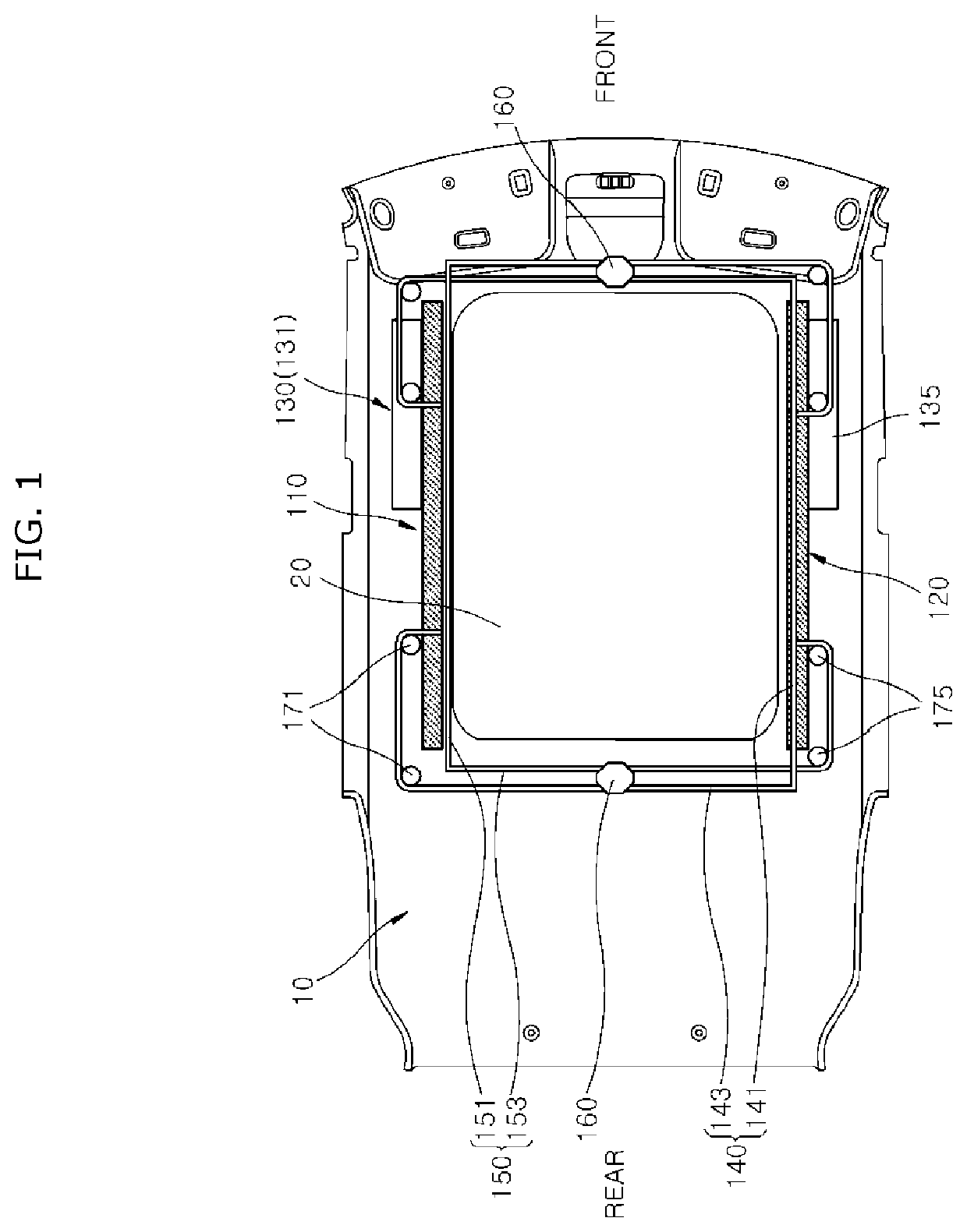
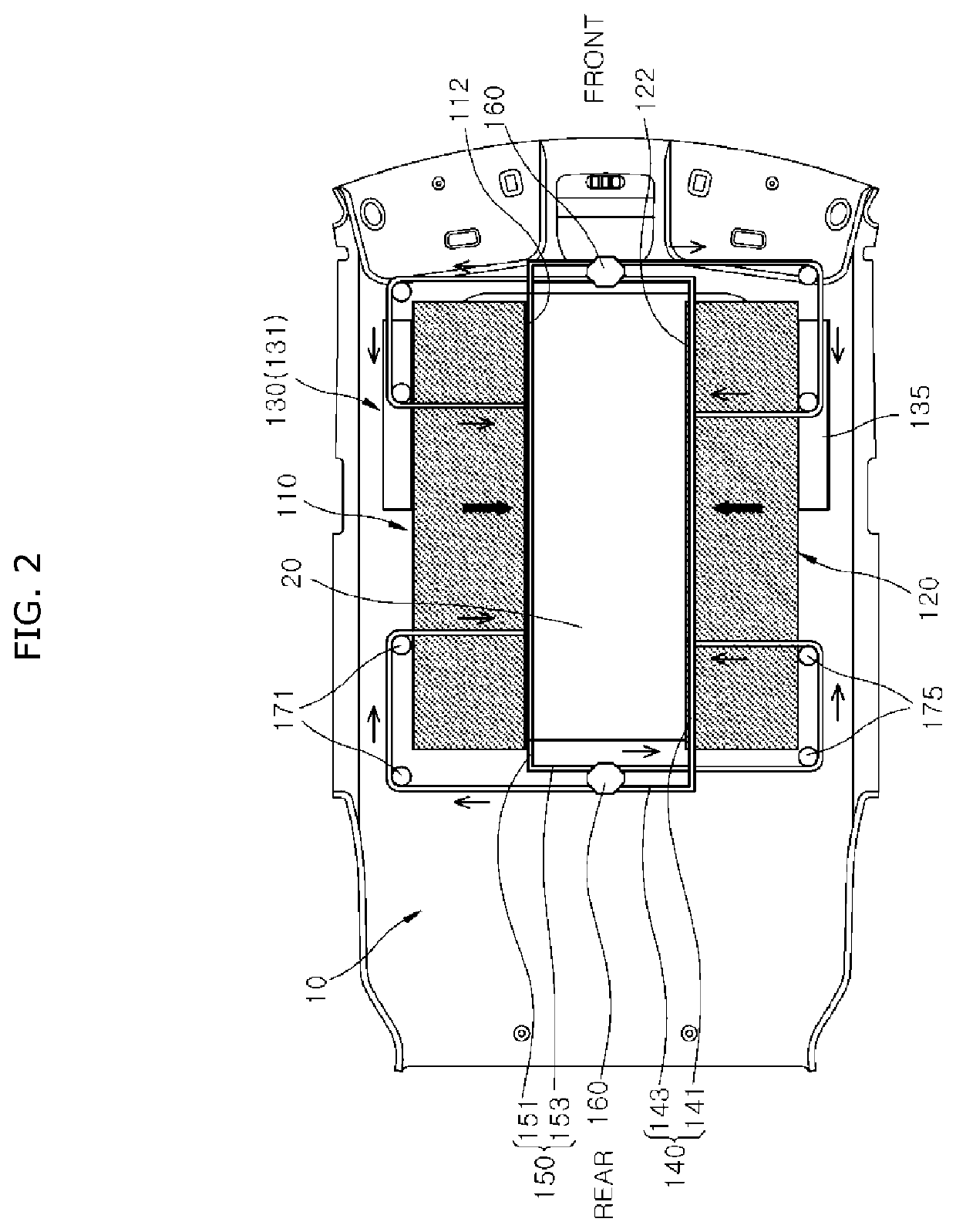
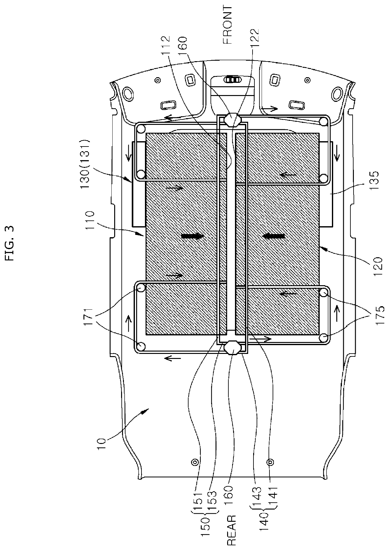
[0034]FIG. 1 is a top view illustrating a roof airbag apparatus according to a first embodiment of the present disclosure. FIG. 2 is a top view illustrating a state in which a first cushion and a second cushion are almost half deployed in the roof airbag apparatus according to the first embodiment of the present disclosure. FIG. 3 is a top view illustrating a state in which the first cushion and the second cushion are fully deployed in the roof airbag apparatus according to the first embodiment of the present disclosure.

[0035]Referring to FIGS. 1 to 3, a roof airbag apparatus according to a first embodiment of the present disclosure includes a first cushion 110, a second cushion 120, a first wire 140, a second wire 150, and guide anchors 160.

[0036]A head lining 10 is installed on a ceiling of a vehicle body, and an opening (not illustrated) is formed in the center of the head lining 10. A pano...

second embodiment

[0064]Next, a roof airbag apparatus according to the present disclosure will be described.

[0065]FIG. 4 is a top view illustrating a roof airbag apparatus according to a second embodiment of the present disclosure. FIG. 5 is a top view illustrating a state in which a first cushion and a second cushion are almost half deployed in the roof airbag apparatus according to the second embodiment of the present disclosure. FIG. 6 is a top view illustrating a state in which the first cushion and the second cushion are fully deployed in the roof airbag apparatus according to the second embodiment of the present disclosure.

[0066]Referring to FIGS. 4 to 6, a roof airbag apparatus according to a second embodiment of the present disclosure includes a first cushion 110, a second cushion 120, a first wire 140, a second wire 150, and guide anchors 160.

[0067]A head lining 10 is installed on a ceiling of a vehicle body, and an opening (not illustrated) is formed in the center of the head lining 10. A p...


PUM


Abstract

A roof airbag apparatus including: a first cushion disposed on one side of a panoramic sunroof in a width direction of the panoramic sunroof and connected to an inflator; a second cushion disposed on the other side of the panoramic sunroof in the width direction and connected to the inflator; a first wire connected to the second cushion and connected to the first cushion to pull the second cushion toward the first cushion when the first cushion is deployed; a second wire connected to the first cushion and connected to the second cushion to pull the first cushion toward the second cushion when the second cushion is deployed; and guide anchors on which the first wire and the second wire are movably supported.

Description

CROSS-REFERENCE TO RELATED APPLICATION[0001]This application claims priority from and the benefit of Korean Patent Application No. 10-2018-0135691, filed on Nov. 7, 2018, which is hereby incorporated by reference for all purposes as if set forth herein.BACKGROUNDField[0002]Exemplary embodiments relates to a roof airbag apparatus, and more particularly, to a roof airbag apparatus in which a pair of cushions can be smoothly deployed because one of the cushions is deployed by a deployment pressure of the other cushion.Discussion of the Background[0003]An airbag apparatus is generally installed in a vehicle for safety of an occupant. A roof airbag apparatus is installed on a rear side of a panoramic roof installed in a ceiling of the vehicle. Guide bars are installed on opposite sides of the roof airbag apparatus in a width direction so as to guide wires. When the roof airbag apparatus is deployed, the roof airbag apparatus is deployed along the guides while the roof airbag apparatus is...

Claims


Application Information

Patent Timeline
IPC IPC(8): B60R21/213B60R21/231B60R21/2338
CPCB60R21/23138B60R21/213B60R2021/23107B60R21/26B60R21/2338B60R2021/161B60R21/214B60R2021/23192B60R21/231B60R2021/23386B60R21/264B60J7/043
Inventor KOO, YOU HOE
Owner HYUNDAI MOBIS CO LTD
Why Eureka
Try Eureka