Knee airbag device for vehicle
- Summary
- Abstract
- Description
- Claims
- Application Information
AI Technical Summary
Benefits of technology
Problems solved by technology
Method used
Image
Examples
first embodiment
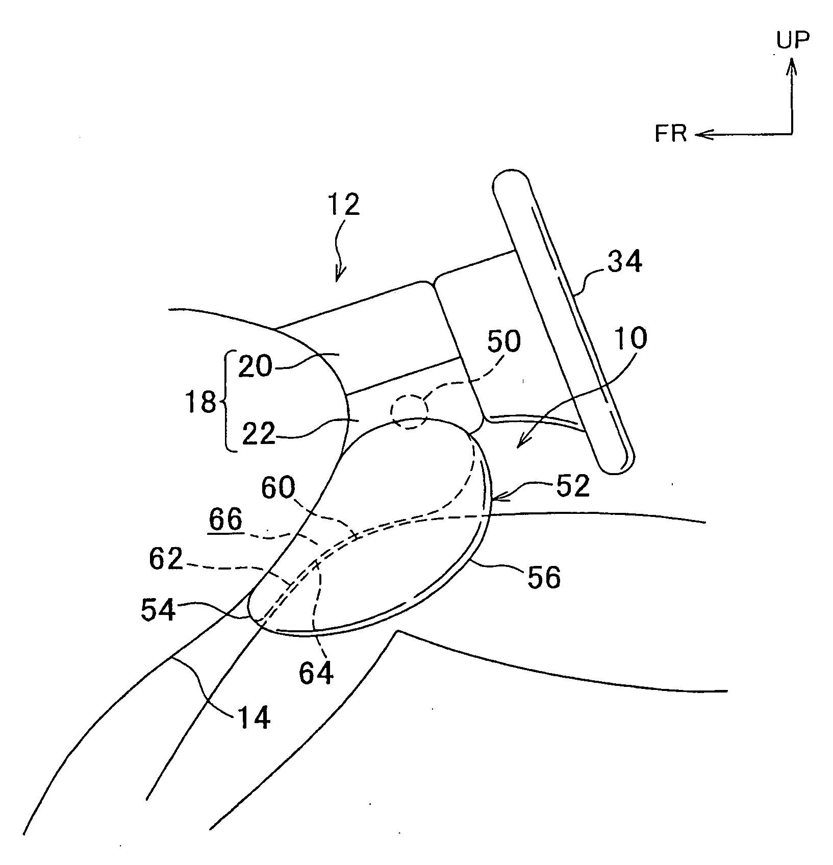
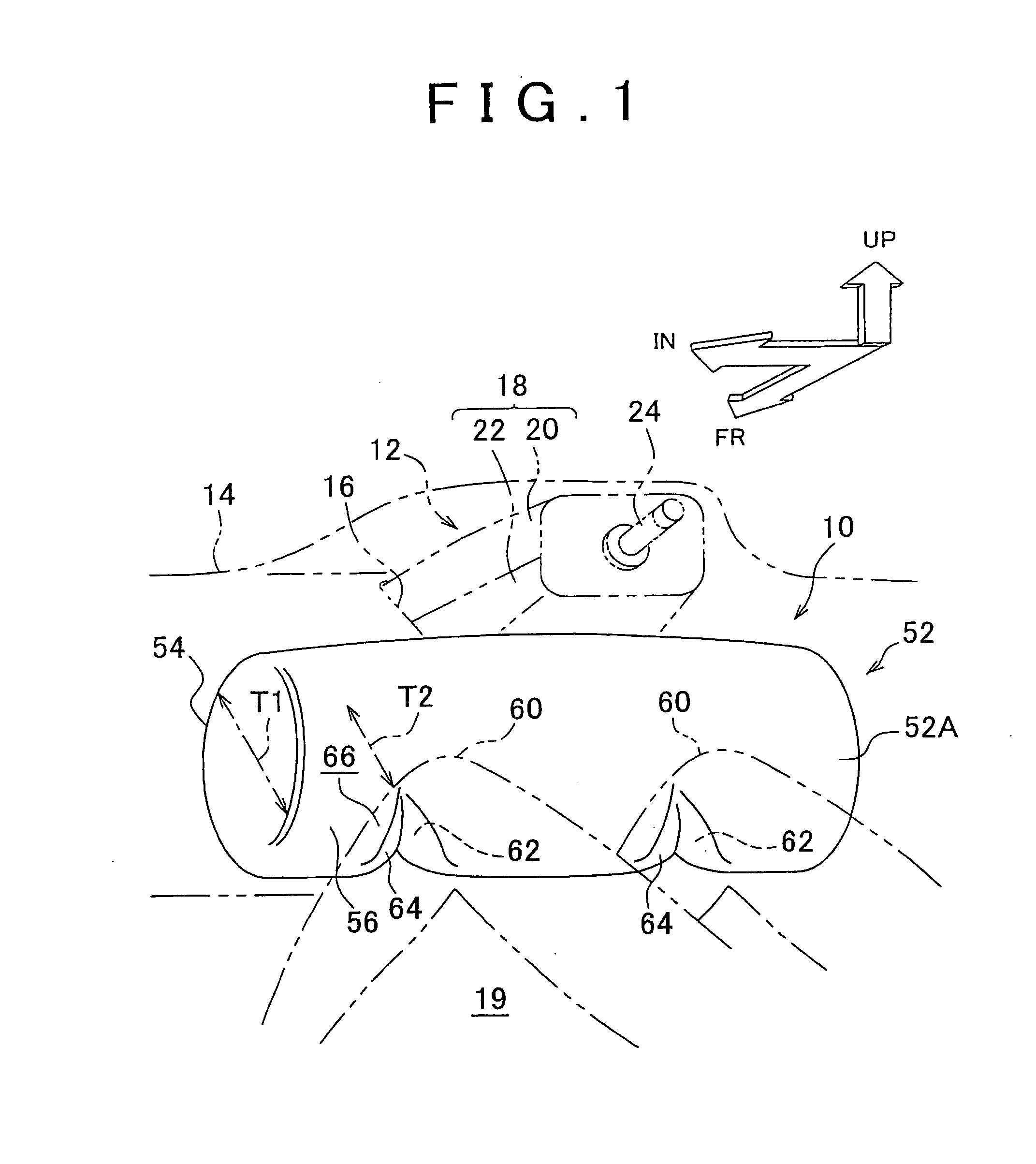
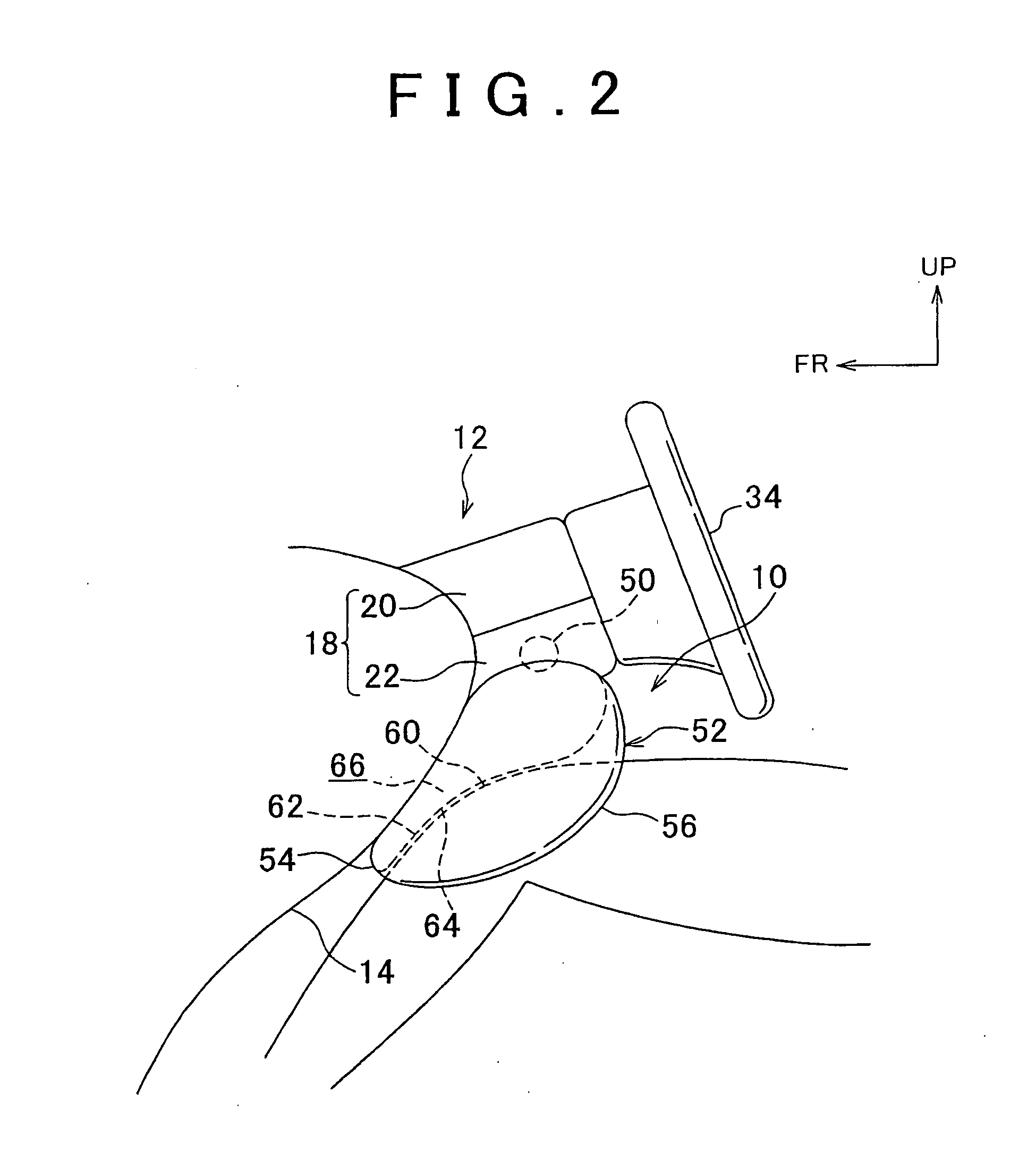
[0032]Hereinafter, a knee airbag device for a vehicle according to a first embodiment of the invention will be described with reference to FIG. 1 to FIG. 3. In FIG. 1, the arrow FR indicates the front of a vehicle. The arrow UP indicates the top of the vehicle. The arrow IN indicates the inside of the vehicle in a vehicle-width direction.
[0033]FIG. 1 is a perspective view showing a knee airbag device according to an embodiment, which is operated, and which is viewed from the rear of the vehicle. FIG. 2 is a lateral view showing the knee airbag device that is operated. FIG. 3A is a plan view showing the configuration of a knee airbag according to the first embodiment. FIG. 3B is a cross sectional view of the main portion of the knee airbag that is inflated and deployed.
[0034]As shown in FIG. 1 to FIGS. 3A and 3B, the knee airbag device 10 is disposed under the rear end of the steering column 12. That is, an opening portion 16 is formed on a portion of the instrument panel 14, which f...
second embodiment
[0048]Hereinafter, a knee airbag device for a vehicle according to a second embodiment of the invention will be described with reference to FIGS. 4A to 4C. The same and corresponding portions as those in the first embodiment will be denoted with the same reference numerals, and the description thereof will be omitted.
[0049]As shown in FIGS. 4A to 4C, in the second embodiment, a knee airbag 70 includes an instrument panel-side foundation cloth 54 and an occupant-side foundation cloth 56. Straps 62 are provided inside the knee airbag 70 at positions in contact portions that contact the knees 60. Each strap 62 has an angular U-shape cross section. The straps 70 may be regarded as the thickness regulation member and the connection member. One side portion 72A of each strap 72 is sewn to the instrument panel-side foundation cloth 54 and the other side portion 72B is sewn to the occupant-side foundation cloth 56. The thickness of the inflated and deployed knee airbag 70 at the positions i...
third embodiment
[0053]Hereinafter, a knee airbag device for a vehicle according to a third embodiment of the invention will be described with reference to FIGS. 5A and 5B. The same and corresponding portions as those in the first embodiment will be denoted with the same reference numerals, and the description thereof will be omitted.
[0054]As shown in FIGS. 5A and 5B, in the third embodiment, a knee airbag 80 includes an instrument panel-side foundation cloth 82 and an occupant-side foundation cloth 84, as in the first embodiment and the second embodiment. In addition, in the third embodiment, each of the instrument panel-side foundation cloth 82 and the occupant-side foundation cloth 84 is formed by cutting cloth so that each of the instrument panel-side foundation cloth 82 and the occupant-side foundation cloth 84 has a shape indented toward the inside of the knee airbag 80 at positions in the contact portions. The instrument panel-side foundation cloth 82 and the occupant-side foundation cloth 84...
PUM
 Abstract
Description
Claims
Application Information
 - R&D
- Intellectual Property
- Life Sciences
- Materials
- Tech Scout
- Unparalleled Data Quality
- Higher Quality Content
- 60% Fewer Hallucinations
Browse by: Latest US Patents, China's latest patents, Technical Efficacy Thesaurus, Application Domain, Technology Topic, Popular Technical Reports.
© 2025 PatSnap. All rights reserved.Legal|Privacy policy|Modern Slavery Act Transparency Statement|Sitemap|About US| Contact US: help@patsnap.com


