Device for tightening and loosening bicycle brake wire

Inactive Publication Date: 2006-11-02
TEKTRO TECH
View PDF1 Cites 8 Cited by
  • Summary
  • Abstract
  • Description
  • Claims
  • Application Information

AI Technical Summary

Benefits of technology

[0008] The primary purpose of the present invention is to provide a device for tightening and loosening a bicycle's brake wire, which is installed between the handbrake operating device and the handbrake assembly of the bicycle. The device is mainly composed of a knob structure, a seat structure, and a tubular element. Where the knob structure and the seat structure join together, the knob structure is configured with a long tooth and a short tooth, and the seat structure is configured with a deep notch and a shallow notch, both matching the shapes and dimensions of the long and short teeth of the knob structure respectively. As such, the total length of the knob and seat structure changes as the knob structure is twisted, which in turn tightens or loosens the brake wire of the bicycle. The gap between the handbrake assembly's brake pads therefore could be narrowed for the handbrake's normal operation, or widened for dismounting the bicycle's wheel quickly and conveniently.
[0009] Another objective of the present invention is to provide a device for tightening and loosening a bicycle's brake wire, which the plastic tubular element with a ring at an end is installed in the device before threading the brake wire through the device. The tubular element on one hand reduces the function from the brake wire's directly rubbing against the device. On the other hand, the tubular element is used to string the knob structure and the seat structure together before they are actually installed on a bicycle. The brake wire's tightening and loosening devices therefore could be shipped from their product plant to the bicycle assembly line, and then installed on a bicycle much more conveniently and easily.

Problems solved by technology

This, however, causes a problem that the wheel is unable to pass through the gap between the brake pads when the wheel is dismounted.
Therefore, an ordinary rider cannot dismount the wheels conveniently and quickly even after the device 10 is operated.

Method used


Image

  • Device for tightening and loosening bicycle brake wire
  • Device for tightening and loosening bicycle brake wire
  • Device for tightening and loosening bicycle brake wire

Examples


Embodiment Construction

[0020] The following descriptions are of exemplary embodiments only, and are not intended to limit the scope, applicability or configuration of the invention in any way. Rather, the following description provides a convenient illustration for implementing exemplary embodiments of the invention. Various changes to the described embodiments may be made in the function and arrangement of the elements described without departing from the scope of the invention as set forth in the appended claims.

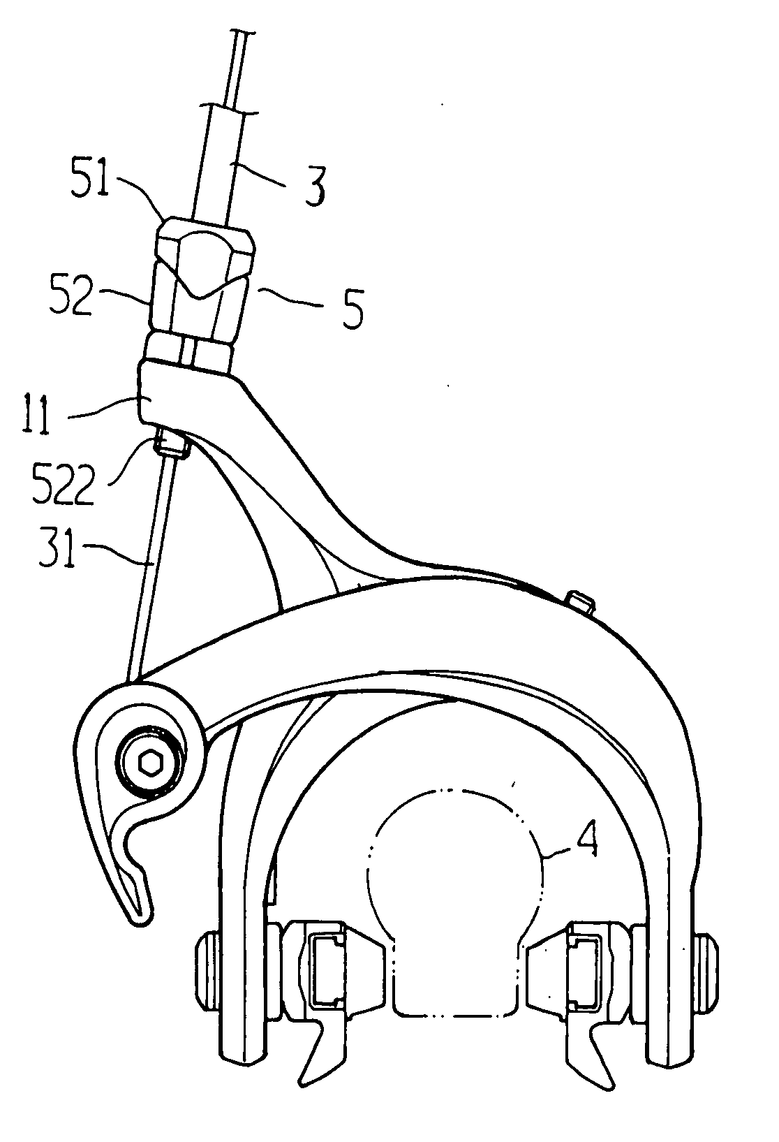
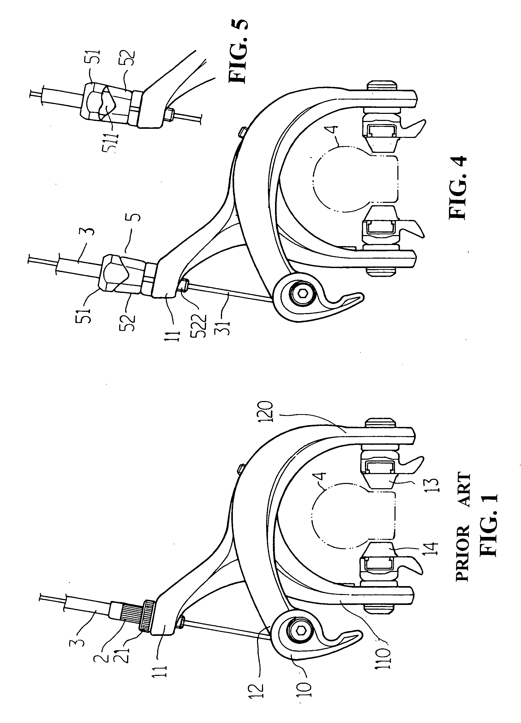
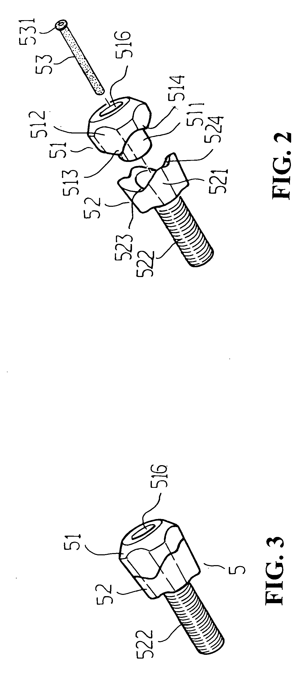
[0021] Please refer to FIGS. 2 to 8. A brake wire tightening and loosening device 5 according to the present invention is composed of a knob structure 51, a seat structure 52, and a tubular element 53. The knob structure 51 has a tubular body 511 with a knob head 512 on the top. The bottom rim of the knob head 512 is configured with at least a long tooth 513 and at least a short tooth 514, all pointed along the knob structure 51's axial direction. On the other hand, the seat structure 52 has a ...


PUM


Abstract

A device for tightening and loosening a bicycle's brake wire is provided, which is installed between a handbrake operating device and a handbrake assembly of the bicycle. The device is mainly composed by a knob structure, a seat structure, and a tubular element. The knob structure and seat structure are configured such that their total length changes as the knob structure is twisted, which in turn tightens or loosens the brake wire of the bicycle. The gap between the handbrake assembly's brake pads therefore could be narrowed for the handbrake's normal operation, or loosened for dismounting the bicycle's wheel quickly and conveniently.

Description

BACKGROUND OF THE INVENTION [0001] (a) Technical Field of the Invention [0002] The present invention generally relates to bicycle handbrakes, and more specifically to a device positioned between the handbrake operating device and the handbrake assembly of a bicycle for fast tightening and loosening the brake wire. [0003] (b) Description of the Prior Art [0004] Generally, on a bicycle, there are devices for fast assembly and disassembly of some parts of the bicycle. Some typical examples include the ones at the hubs of the front and rear wheels to dismount the wheels quickly. Another one is installed under the saddle and around the seat pillar so that the height of the saddle could be adjusted quickly. There are also ones for tightening and loosening the brake wires quickly. [0005] A bicycle handbrake system usually contains a handbrake operating device installed on the handlebar of the bicycle, a handbrake assembly installed at the two sides of the rim of the front or rear wheel, an...

Claims


Application Information

Patent Timeline
IPC IPC(8): B62L3/00
CPCB60T11/046Y10T74/20462F16C1/226B62L3/00F16C2326/20
Inventor TSAI, SZU-FANG
Owner TEKTRO TECH
Why Eureka
Try Eureka