Industrial bag lift loop assembly

a technology of lifting loops and bags, applied in the field of lifting loops, can solve the problems of affecting the safety of persons exposed to the products being transported in bulk bags, and affecting the safety of persons exposed to the materials contained within the bags, and achieve the effect of weakening the bag fabri

Inactive Publication Date: 2020-05-21
AMERIGLOBE
View PDF0 Cites 2 Cited by
  • Summary
  • Abstract
  • Description
  • Claims
  • Application Information

AI Technical Summary

Benefits of technology

The present invention solves problems in the prior art with stitched lift loops by providing an apparatus and method for a flexible bag with a lifting assembly. The lifting assembly includes one or more lift members that are coupled to a fabric layer, which is then coupled to the bag. This eliminates the need for stitching the lift loops directly to the bag fabric and thus avoids weakening the bag. The lift loops are also placed on a separate piece of fabric that can tear away from the bag without damaging the bag. This prevents the problem of the lift loops tearing away from the bag and causing large holes in the product containment area, which could lead to the loss of the product and potentially harm people handling the bag. The separate piece of fabric is heat fused to the bag fabric so that if the coupler fails, the bag fabric remains undamaged.

Problems solved by technology

As discussed above, in the prior art, if a bag with lift loops stitched or sewn directly to bag fabric is improperly handled, e.g., by less than all four lift loops, the lift loops often tear away from the bag by pulling and breaking portions of the side wall from the bag.
This causes large holes in the bulk bag product containment area allowing the product to spill out of the bag and / or contamination to enter the bag.
This often causes the loss of the product that was being transported in the bulk bag.
If the product was considered to be hazardous, then a spill containment action would be needed, and persons exposed to the materials that were contained within the bag could be harmed.

Method used


Image

  • Industrial bag lift loop assembly
  • Industrial bag lift loop assembly
  • Industrial bag lift loop assembly

Examples


Embodiment Construction

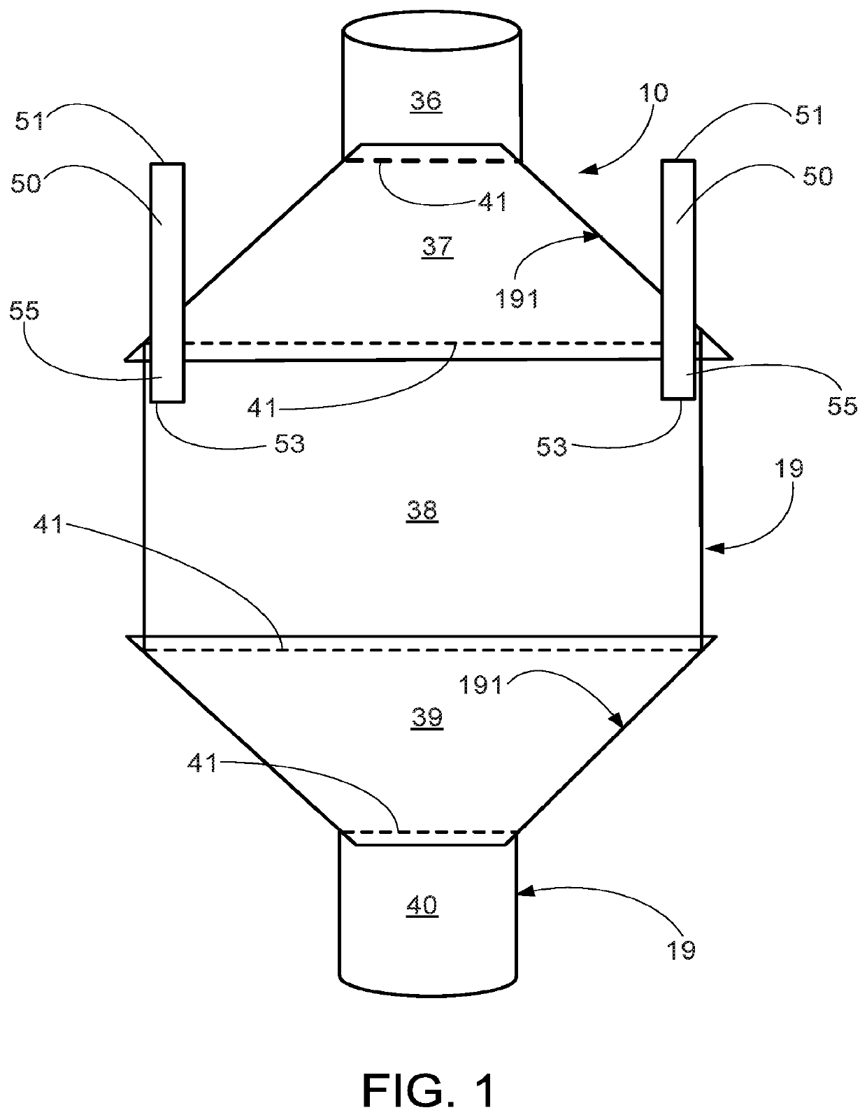
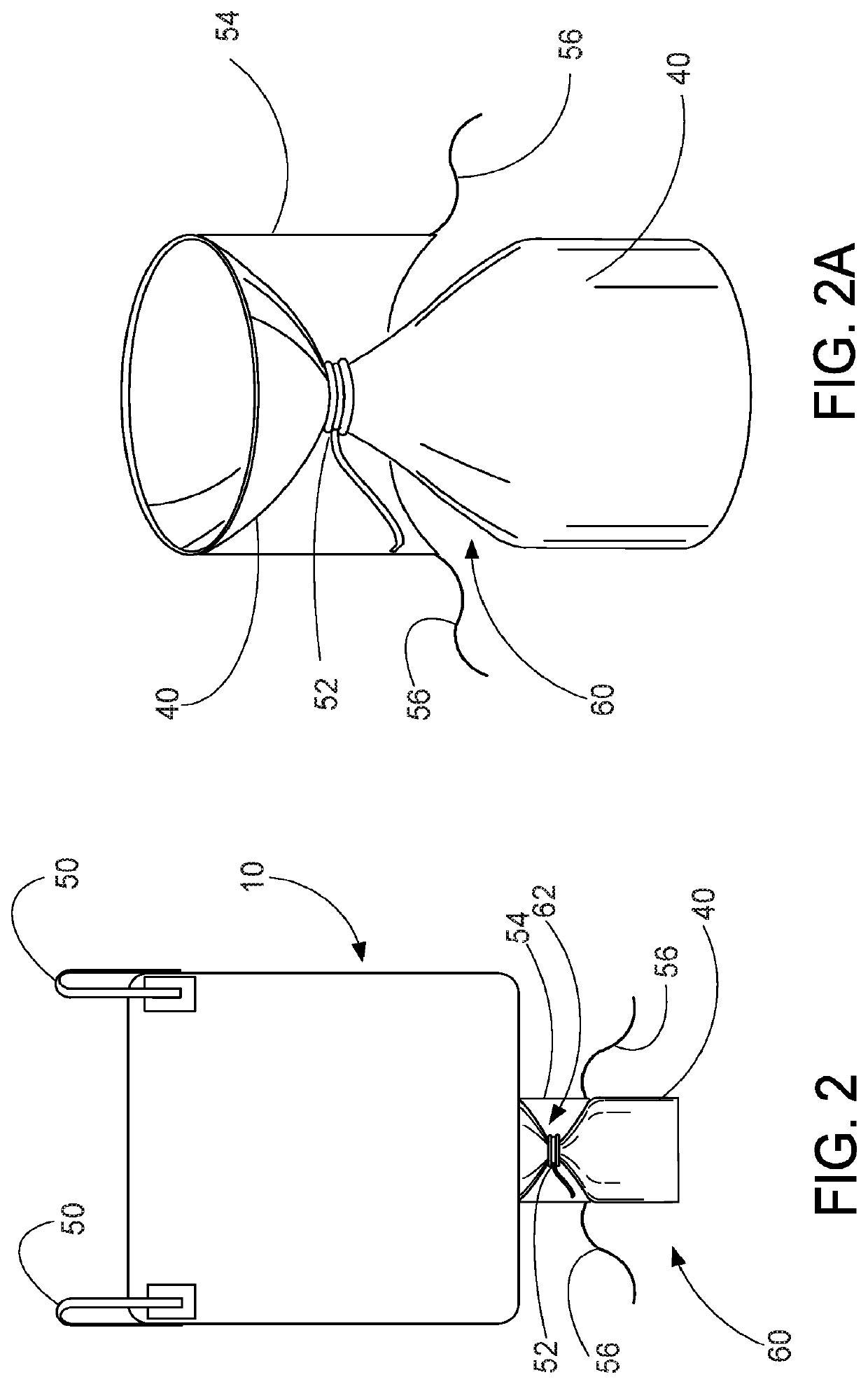
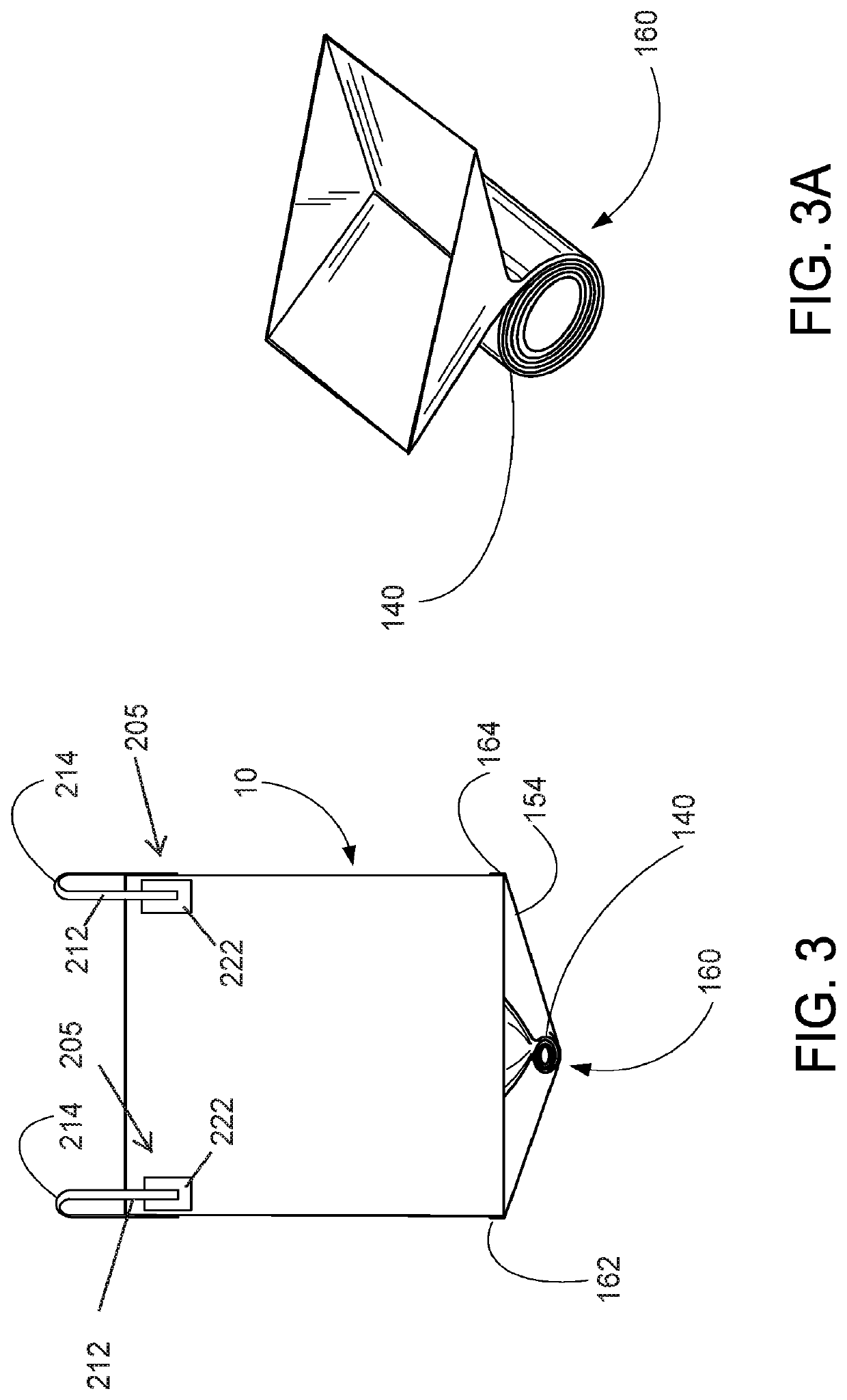
[0127]In the drawings and description that follow, like parts are typically marked throughout the specification and drawings with the same reference numerals. The drawing figures are not necessarily to scale. Certain features of the disclosed embodiments may be shown exaggerated in scale or in somewhat schematic form and some details of conventional elements may not be shown in the interest of clarity and conciseness. The present disclosure is susceptible to embodiments of different forms. Specific embodiments are described in detail and are shown in the drawings, with the understanding that the present disclosure is to be considered an exemplification of the principles of the disclosure, and is not intended to limit the disclosure to that illustrated and described herein. It is to be fully recognized that the different teachings of the embodiments discussed below may be employed separately or in any suitable combination to produce desired results.

[0128]Unless otherwise specified, i...


PUM


Abstract

A lifting assembly and method for a flexible bag includes one or more lift members, wherein each lift member is coupled to a layer of material, e.g., a fabric layer. The fabric layer can be coupled to a flexible bag wherein the fabric layer is an intermediate layer between the lift member and the flexible bag. The fabric layer can be heat fused or otherwise coupled to a bag without stitching or sewing, which eliminates the creation of sew or stitch holes that breach a containment area of the bag and which can weaken the bag fabric. The one or more lift members, however, can be sewn or stitched to one or more intermediate layers.

Description

CROSS-REFERENCE TO RELATED APPLICATIONS[0001]Priority to and / or the benefit of U.S. Provisional Patent Application Ser. No. 62 / 269,087, filed 17 Dec. 2015, which is hereby incorporated herein by reference, is hereby claimed.[0002]Priority to and / or the benefit of U.S. Provisional Patent Application Ser. No. 62 / 419,317, filed 8 Nov. 2016, which is hereby incorporated herein by reference, is hereby claimed.[0003]This application is related to U.S. patent application Ser. No. 15 / 345,452, filed on 7 Nov. 2016, which claims the benefit of and / or priority to U.S. Provisional Patent Application Ser. No. 62 / 252,270, filed on Nov. 6, 2015 and U.S. Provisional Patent Application Ser. No. 62 / 269,087, filed 17 Dec. 2015, each of which is hereby incorporated herein by reference.STATEMENT REGARDING FEDERALLY SPONSORED RESEARCH OR DEVELOPMENT[0004]Not applicableREFERENCE TO A “MICROFICHE APPENDIX”[0005]Not applicableBACKGROUND OF THE INVENTION1. Field of the Invention[0006]The present invention re...

Claims


Application Information

Patent Timeline
Patent Type & Authority Applications(United States)
IPC IPC(8): B65D88/16
CPCB65D88/1668B65D88/1681
Inventor DUNLAP, CLIFFORDSCHNAARS, SR., DANIEL R.
Owner AMERIGLOBE
Why Eureka
Try Eureka