Composition for forming a thermoelectric film and thermoelectric film containing the same

Pending Publication Date: 2020-05-28
KOREA INST OF MATERIALS SCI
View PDF2 Cites 0 Cited by
  • Summary
  • Abstract
  • Description
  • Claims
  • Application Information

AI Technical Summary

Benefits of technology

[0013]One object of the present invention is to solve the pore problem and a low electrical property which occur in manufacturing a thick film-type thermoelectric film using an existing thermoelectric powder paste. In order to solve the abovementioned problem, the inventors of the present inventi

Problems solved by technology

However, in case of a thin film element among vertical-type thermoelectric elements, it is difficult to continuously maintain the temperature difference between upper and lower side in ther element, and in case of a bulk-type thermoelectric element, it is relatively easy to maintain a temperature difference, but there is a limitation in practical use due to a large volume.
However, due to a lower thermoelectric performance index than a bulk material and particularly, due to low electrical conductivity in most results, the thick film-type thermoelectric element is limited in practical application despite its high necessity.
In particular, when the electrical conductivity σ is low, Joule heat is generated due to resistance so that power generation using a temperature difference is not efficiently performed, and thus, there is a limitation in using the thick film-type thermoelectric element for power generation.
Actually, in case of existing flexible thermoelectric materials manufactured by using a thermoelectric paste

Method used


Image

  • Composition for forming a thermoelectric film and thermoelectric film containing the same
  • Composition for forming a thermoelectric film and thermoelectric film containing the same
  • Composition for forming a thermoelectric film and thermoelectric film containing the same

Examples


Example

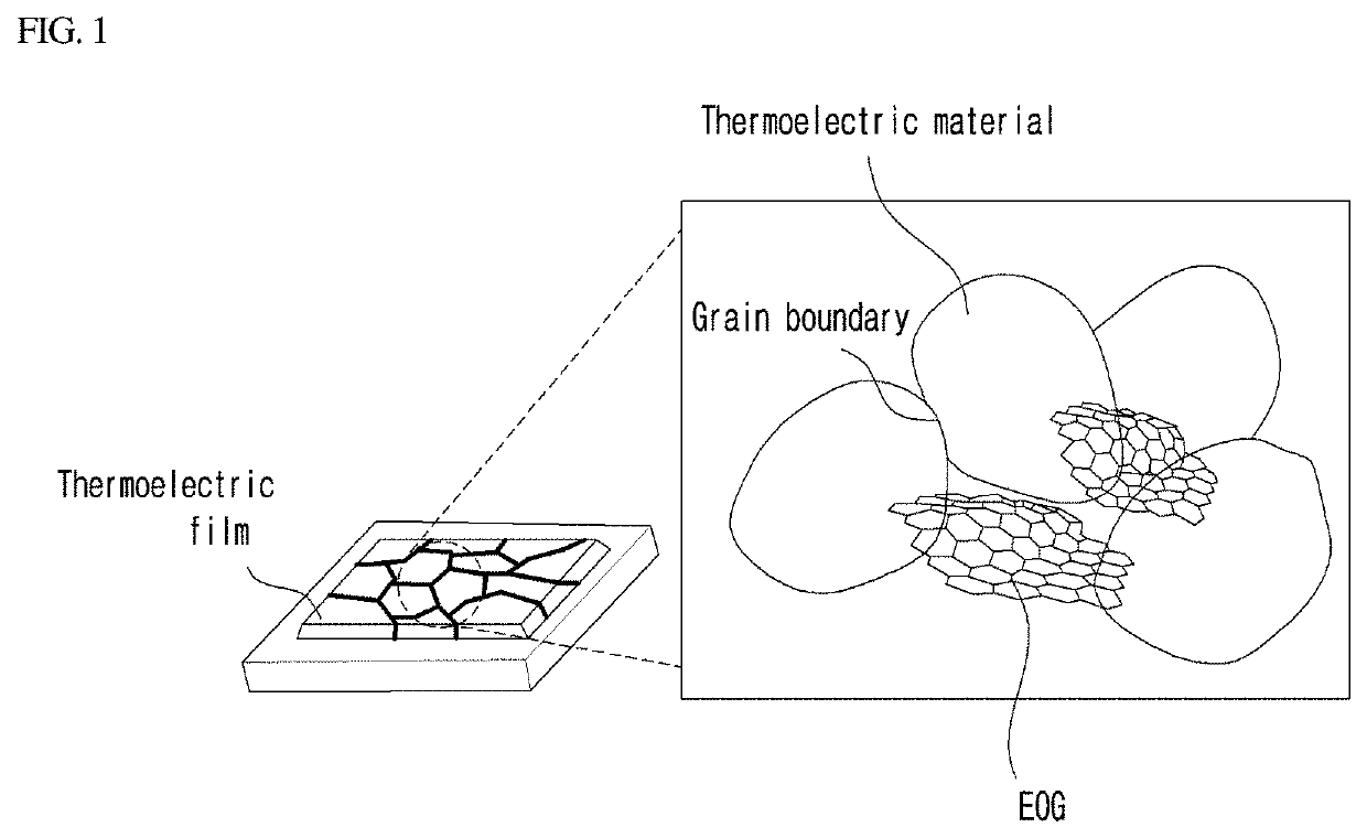
[0055]A thermoelectric film was manufactured by performing example 1 in the same manner except for using 0.6 wt % of EOG in step 1 of example 1 and using 79.2 wt % of the thermoelectric powder. When the graphene oxide used for manufacturing remains as it is, the EOG inside the thermoelectric film is approximately 0.8 wt %.

Thin Film Manufacturing-3

[0056]A thermoelectric film was manufactured by performing example 1 in the same manner except for using 0.9 wt % of EOG in step 1 of example 1 and using 78.8 wt % of the thermoelectric powder. When the graphene oxide used for manufacturing remains as it is, the EOG inside the thermoelectric film is approximately 1.2 wt %.

Thin Film Manufacturing-4

[0057]A thermoelectric film was manufactured by performing example 1 in the same manner except for using 1.3 wt % of EOG in step 1 of example 1 and using 78.4 wt % of the thermoelectric powder. When the graphene oxide used for manufacturing remains as it is, the EOG inside the thermoelectric film...

Example

Comparative Example 1

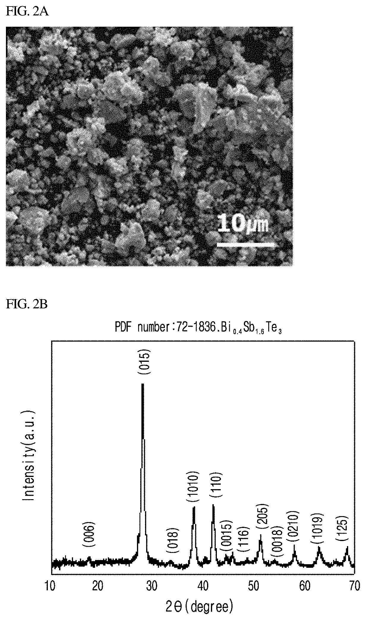
[0060]Step 1: A thermoelectric film forming paste was manufactured by mixing 20 wt % of an organic binder (1 wt % of ethyl cellulose and 99 wt % of a-terpineol) and 80 wt % of thermoelectric powder composed of Bi—Sb—Te.

[0061]Step 2: A thick film-shaped thermoelectric film was manufactured by manually printing the thermoelectric film forming paste manufactured in step 1 above by a thickness of 400 μm, removing the organic binder present inside through two-stage heat treatment (at a temperature of 60° C. for two hours and at a temperature of 400° C. for four hours), and performing sintering between thermoelectric powder particles.

Example

Comparative Example 2

[0062]Step 1: A thermoelectric film forming paste was manufactured by mixing: a paste in which 0.9 wt % of a graphene oxides and water were mixed; 20 wt % of an organic binder (1 wt % of ethyl cellulose and 99 wt % of a-terpineol); and 78.8 wt % of thermoelectric powder composed of Bi—Sb—Te.

[0063]Step 2: A thick film-shaped thermoelectric film was manufactured by manually printing the thermoelectric film forming paste manufactured in step 1 above by a thickness of 400 μm, removing the organic binder present inside through two-stage heat treatment (at a temperature of 60° C. for two hours and at a temperature of 400° C. for four hours), and performing sintering between thermoelectric powder particles. When the graphene oxides used for manufacturing remain as it is, the graphene oxide inside the thermoelectric film is approximately 1.2 wt %.


PUM


Abstract

Disclosed is a composition for forming a thermoelectric film, the composition comprising an edge-oxidized graphene oxide, wherein the edge-oxidized graphene oxide is dispersed in a thermoelectric material.

Description

CROSS-REFERENCES TO RELATED APPLICATION[0001]This patent application claims the benefit of priority from Korean Patent Application No. 10-2018-0123223, filed on Oct. 16, 2018, the contents of which are incorporated herein by reference.BACKGROUND OF THE INVENTION1. Field of the Invention[0002]The present disclosure relates to a composition for forming a thermoelectric film and a thermoelectric film containing the same.2. Description of the Related Art[0003]Thermoelectric technology is a mutually reversible energy converting technology with which electricity is generated through a temperature difference or conversely, a temperature difference is generated by using potential difference. Thermal energy harvesting with which electricity is obtained from discharged or waste heat is enabled by using the Seebeck effect that is a thermoelectric phenomenon in which when a temperature difference is present, electricity is generated. Conversely, when using the Peltier effect with which a temper...

Claims


Application Information

Patent Timeline
IPC IPC(8): H01L35/26H01L35/34
CPCH01L35/26H01L35/34H10N10/857H10N10/01H10N10/80H10N10/853H10N10/855H10N10/852
Inventor KIM, KYUNG TAEJUNG, BYUNG MUN
Owner KOREA INST OF MATERIALS SCI
Why Eureka
Try Eureka