

Electric wire fixing structure, electrical connection box, and wire harness
- Summary
- Abstract
- Description
- Claims
- Application Information
AI Technical Summary
Benefits of technology
Problems solved by technology
Method used
Image

Examples
Embodiment Construction
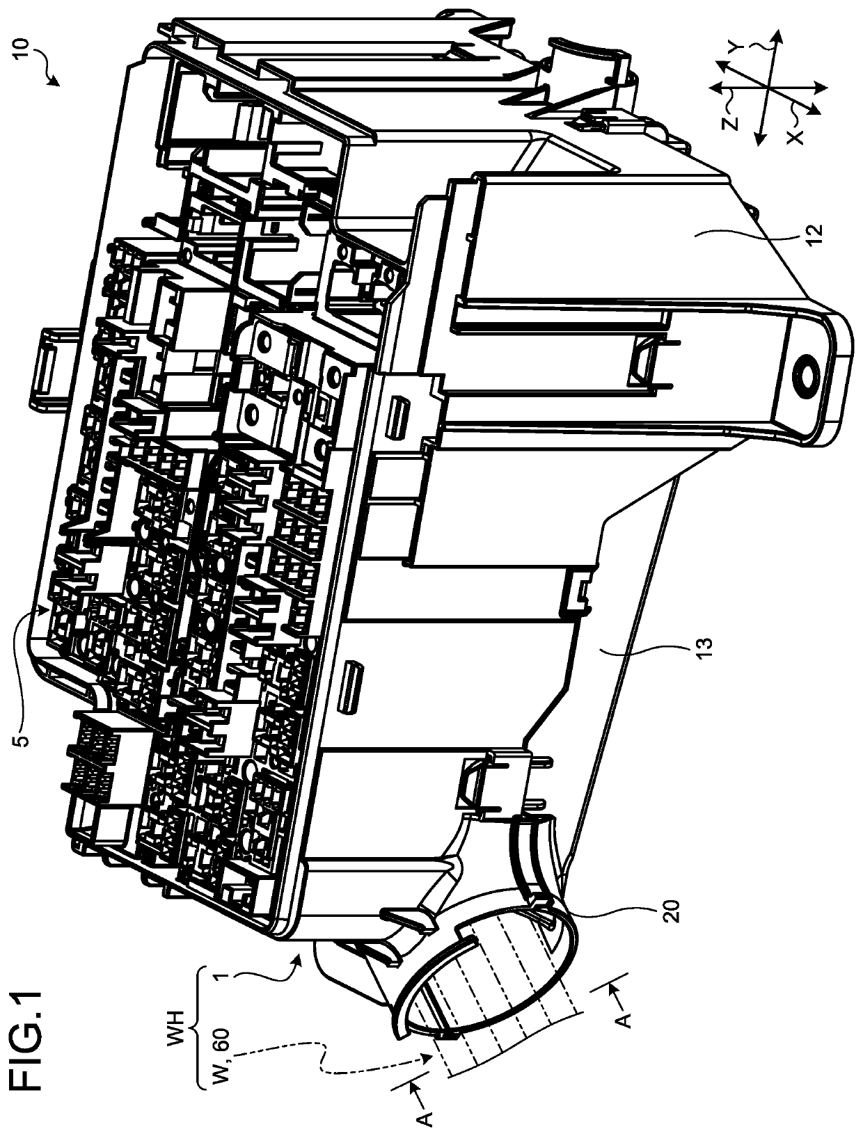
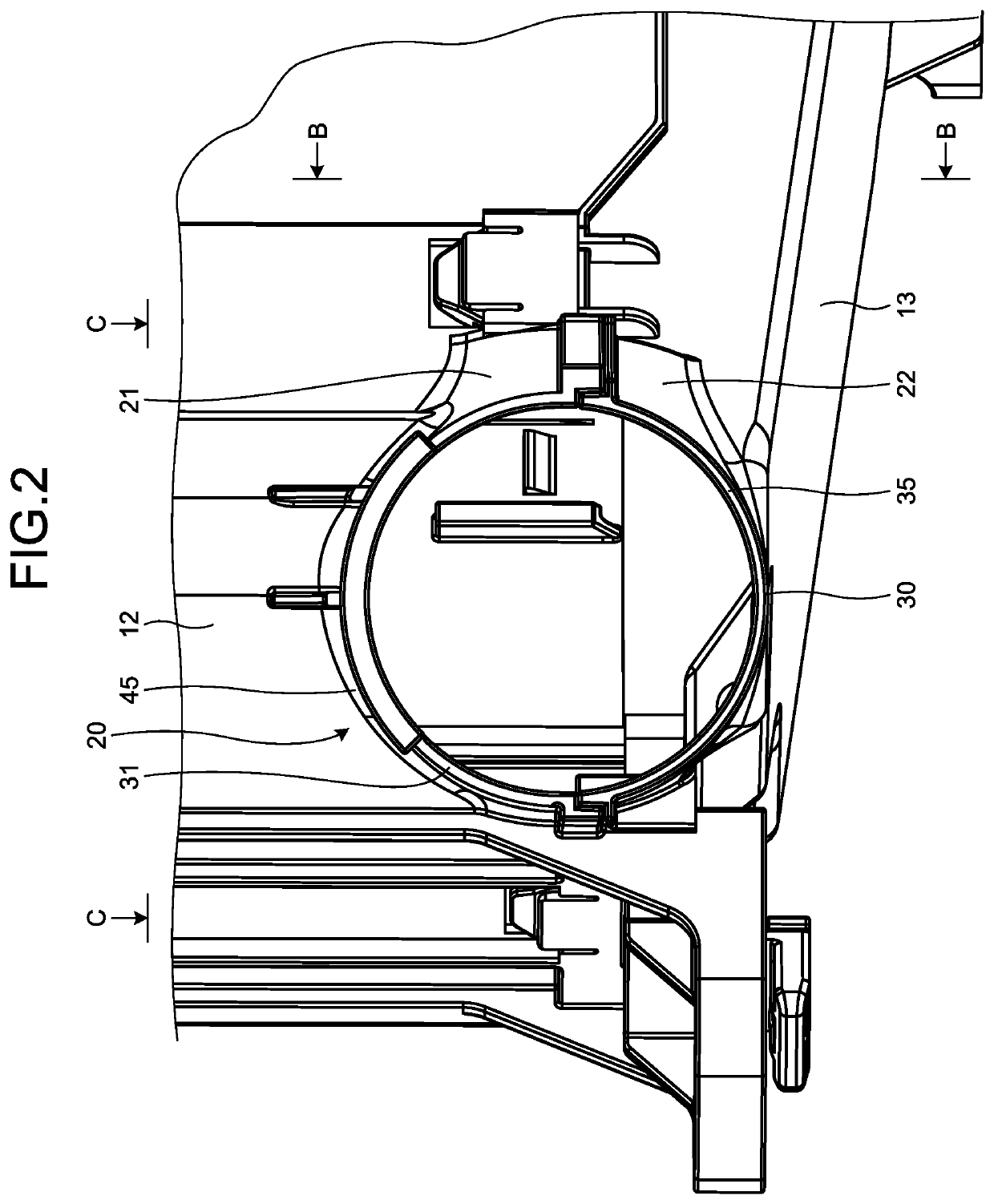
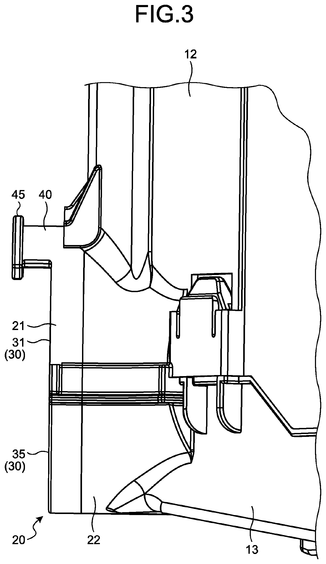
[0022]Hereinafter, embodiments of an electric wire fixing structure, an electrical connection box, and a wire harness according to the present invention will be described in detail with reference to the drawings. Note that the present invention shall not be limited by the embodiments. Furthermore, constituents in the following embodiments include constituents that can be replaced by the constituents in the embodiments and are easily conceivable by a person skilled in the art, or constituents essentially identical to the constituents in the embodiments.
[0023]Note that, in the following descriptions, a horizontal direction under a state in which an electrical connection box 1 is arranged in a normal usage mode is defined as a horizontal direction in the present embodiment; an upward direction under the above-mentioned state is described as an upward direction or an upper side in the present embodiment; and a downward direction under the above-mentioned state is described as a downward...
PUM
 Abstract
Description
Claims
Application Information