Industrial digital barcode scanner

a barcode scanner and industrial technology, applied in the direction of instruments, instruments, stands/trestles, etc., can solve the problems of user's hand being pinched, unsuitable for extended use cycles, and interfering with the operation of the positioning mechanism

Active Publication Date: 2020-07-16
ZEBRA TECH CORP
View PDF5 Cites 9 Cited by
  • Summary
  • Abstract
  • Description
  • Claims
  • Application Information

AI Technical Summary

Problems solved by technology

Some of these positioning systems may be unreliable and thus unsuitable for extended use cycles, and may have exposed components that are exposed to the elements (e.g., dirt and...

Method used


Image

  • Industrial digital barcode scanner
  • Industrial digital barcode scanner
  • Industrial digital barcode scanner

Examples


Embodiment Construction

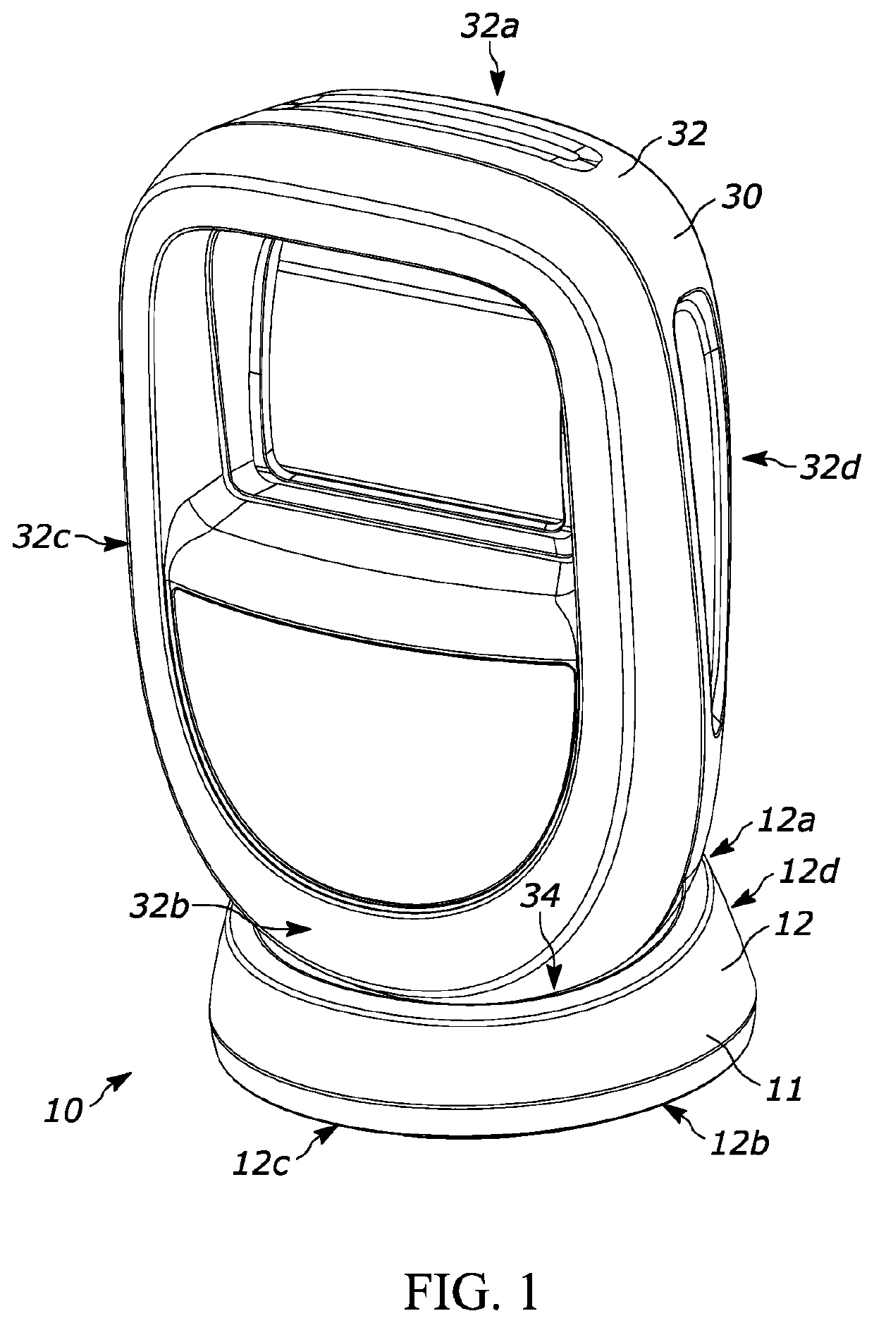
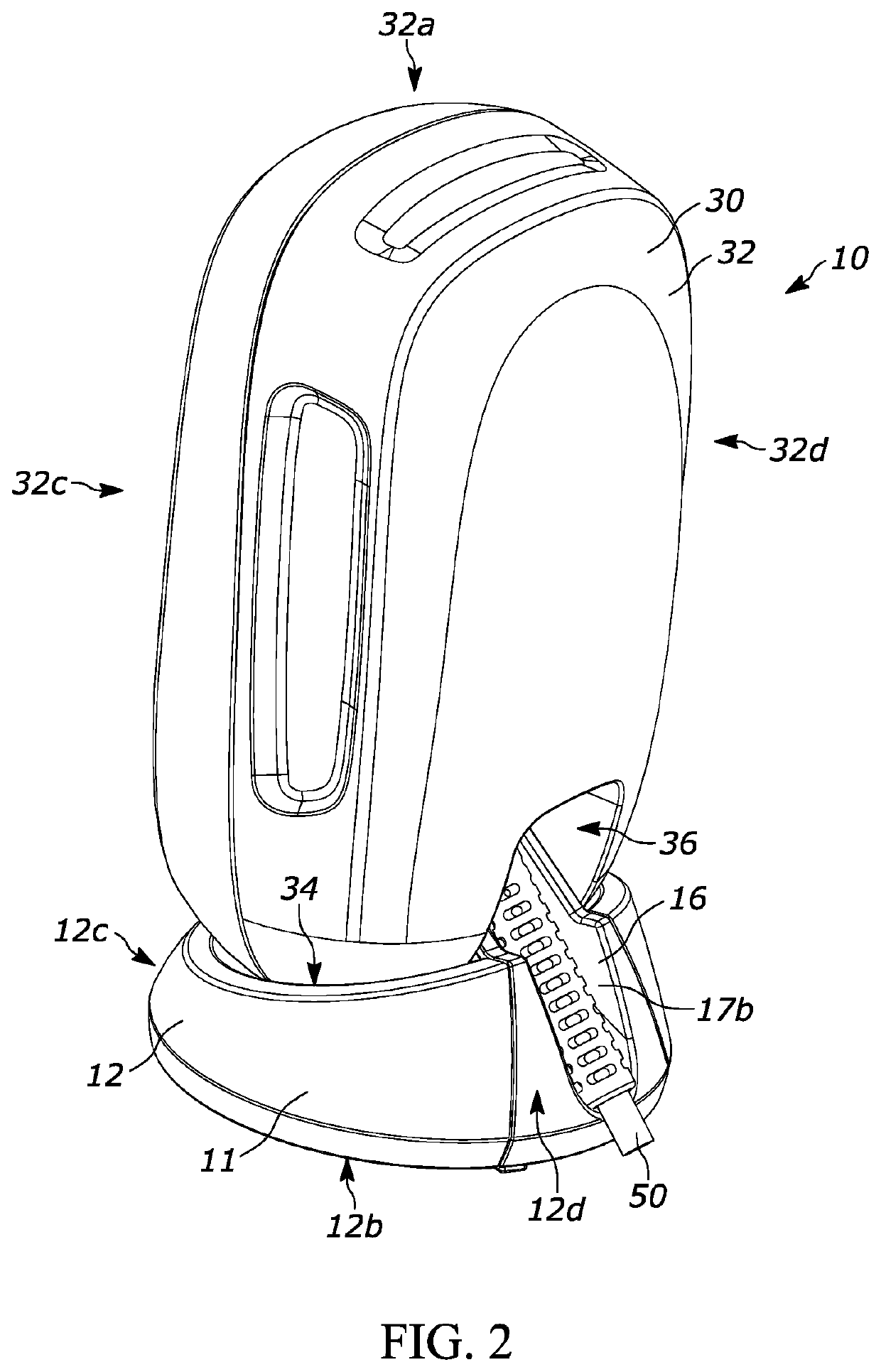
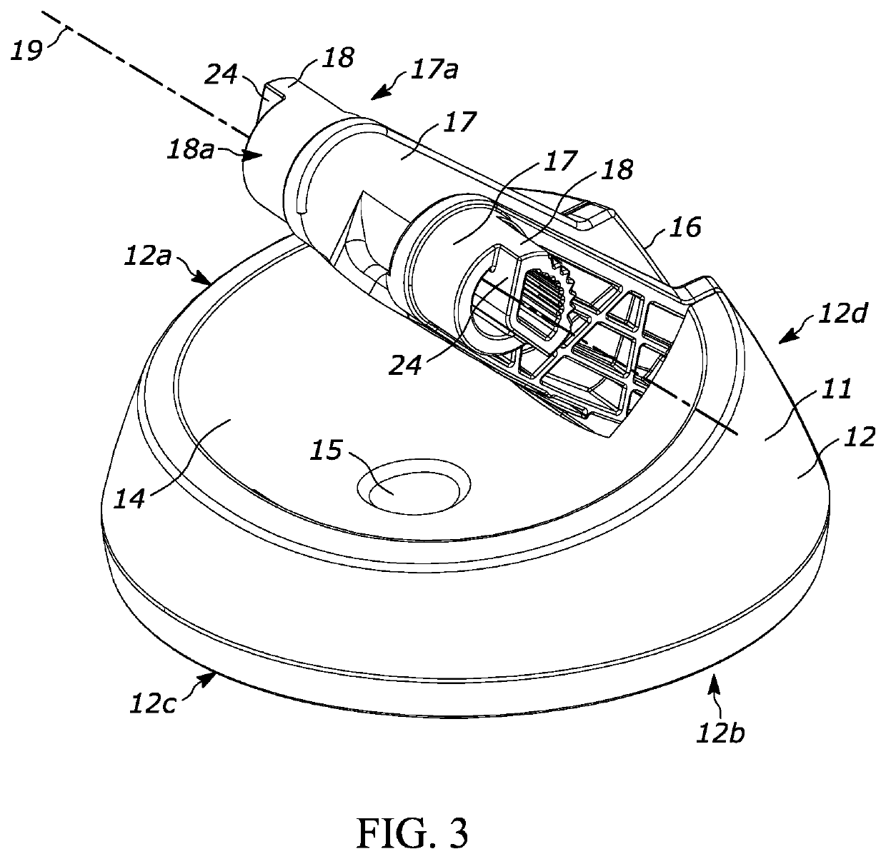
[0013]In an embodiment, the present application provides a barcode scanner assembly for capturing at least one object appearing in a field of view (FOV) that includes a base defining a curved base surface and a scanner enclosure being mechanically coupled to the base. The scanner enclosure includes a top portion and a bottom portion opposite the top portion. The bottom portion of the scanner enclosure is positioned proximate to the base. The bottom portion of the scanner enclosure includes a curved scanner enclosure surface. The curved base surface and the curved scanner enclosure surface are nested such that a clearance of less than approximately 5 mm is formed between the curved base surface and the curved scanner enclosure surface. In some examples, the curved base surface is convex and the curved scanner enclosure surface is concave. In other examples, the curved base surface is concave and the curved scanner enclosure surface is convex.

[0014]In another implementation, a barcode...


PUM


Abstract

A barcode scanner assembly for capturing at least one object appearing in a field of view (FOV) is provided that includes a base defining a curved base surface and a scanner enclosure being mechanically coupled to the base. The scanner enclosure includes a top portion and a bottom portion opposite the top portion. The bottom portion of the scanner enclosure is positioned proximate to the base. The bottom portion of the scanner enclosure includes a curved scanner enclosure surface. The curved base surface and the curved scanner enclosure surface are nested such that a clearance of less than approximately 5 mm is formed between the curved base surface and the curved scanner enclosure surface.

Description

BACKGROUND OF THE INVENTION[0001]Barcode and other scanning devices generally capture images within a given field of view (FOV). In some instances, handheld devices may be used to capture images of objects positioned at varying distances from the device. In such environments, handheld devices may be selectively positioned by a user to assist with capturing a suitable image of the object. Such systems typically include a rotational positioning mechanism that allows a portion of the scanning device to move in order to position the FOV to capture images of desired objects. Some of these positioning systems may be unreliable and thus unsuitable for extended use cycles, and may have exposed components that are exposed to the elements (e.g., dirt and grime) which may lead to interfering with operation of the positioning mechanism. Further, existing mechanisms may include gaps between materials in which a user's hand may be pinched.[0002]Accordingly, there is a need for improved systems, m...

Claims


Application Information

Patent Timeline
IPC IPC(8): G06K7/10G06K7/04
CPCG06K7/04G06K7/109G06K7/1098G06K7/10881F16M11/10F16M2200/024G06K2007/10524
Inventor HANDSHAW, DARRAN MICHAELSIECKOWSKI, STEVEN D.ZHAO, WANCHENGPOTTER, JASON Y.HACKETT, EDWARD ANTHONY
Owner ZEBRA TECH CORP
Why Eureka
Try Eureka