Transceiver device for a bus system and operating method therefor

a bus system and transceiver technology, applied in bus networks, digital transmission, data switching networks, etc., can solve the problem of comparatively complex masking elements

Active Publication Date: 2021-01-14
ROBERT BOSCH GMBH
View PDF12 Cites 5 Cited by
  • Summary
  • Abstract
  • Description
  • Claims
  • Application Information

AI Technical Summary

Benefits of technology

[0004]It is an object of the present invention to improve a transceiver device of the aforementioned type and an ope

Problems solved by technology

The masking element is

Method used


Image

  • Transceiver device for a bus system and operating method therefor
  • Transceiver device for a bus system and operating method therefor
  • Transceiver device for a bus system and operating method therefor

Examples


Embodiment Construction

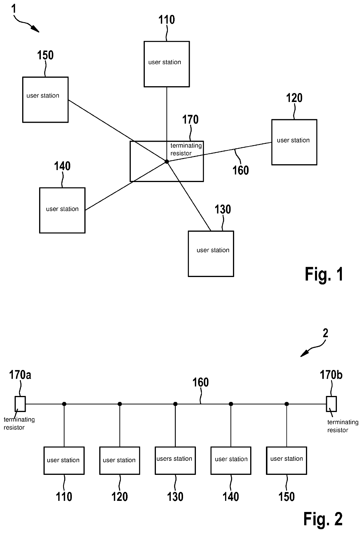
[0030]FIG. 1 schematically shows a simplified block diagram of a bus system 1 according to one specific embodiment of the present invention, which may be used in a vehicle, in particular, in a motor vehicle, an aircraft, etc. or in an industrial robot, etc. Bus system 1 in FIG. 1 has a first user station 110, a second user station 120, a third user station 130, a fourth user station 140, a fifth user station 150, a bus line 160 and a terminating resistor 170, user stations 110 through 150 being situated in a star-shaped topology. Bus system 1 may, for example, be a CAN bus system or a CAN FD bus system, etc. Bus system 1 in the present exemplary embodiment is designed, in general, for a communication in which at least an exclusive, collision-free access of one of user stations 110 through 150 to bus line 160 is at least temporarily ensured. First user station 110 may, for example, be a control unit of a motor vehicle. Second, fourth and fifth user stations 120, 140, 150 may, for exa...


PUM


Abstract

A transceiver device for a bus system. The transceiver device includes first and second bus terminals for connection to first and second signal line of the bus system, and a transmitting unit for outputting a bus transmission signal to the first and second bus terminals. The transceiver device includes an input connection for receiving a transmission input signal useable for controlling an operating state of the transmitting unit, and a detection device, which to detect the presence of a first predefinable condition and, if the first predefinable condition is present, to interconnect the first and second bus terminals via a predefinable electrical resistance for a predefinable first period of time.

Description

FIELD[0001]The present invention relates to a transceiver device for a bus system, the transceiver device including a first bus terminal for connection to a first signal line of the bus system, a second bus terminal for connection to a second signal line of the bus system and a transmitting unit for outputting a bus transmission signal to the first and second bus terminals.[0002]The present invention further relates to a method for operating such a transceiver device.BACKGROUND INFORMATION[0003]A device and a method are described in DE 102015222334A1 for selectively masking bus oscillations when receiving data via a bus system. The conventional device provides a masking element for masking oscillations of the bus signal. The masking element is comparatively complex.SUMMARY[0004]It is an object of the present invention to improve a transceiver device of the aforementioned type and an operating method therefor to the extent that the aforementioned disadvantages of the related art are ...

Claims


Application Information

Patent Timeline
IPC IPC(8): H04L12/413H04L12/40H04L25/02
CPCH04L12/4135H04L12/40013H04L2012/40215H04L25/0272H04L12/4013H04L12/40
Inventor MUTTER, ARTHURWALKER, STEFFEN
Owner ROBERT BOSCH GMBH
Why Eureka
Try Eureka